
PRE-REQUIREMENT:
1. This modification allows you to easily install an M.2 NVMe SSD 2230/2242 to your A1707 15-inch MacBook Pro Touchbar 2016 & 2017.
2. The full list of compatible SSDs will be sent only after you purchased the adapter here(to avoid seller jacking up SSD price): Tindie A1707
3. By all means this mod should be performed to a good working MacBook(no other issue other than SSD issue), it is intended to add value to the Mac, not further downgrading it to a non-working state. So please make sure you are aware of your soldering capabilites and the requirement it takes to perform all these soldering steps successfully. We WILL NOT be responsible if you messed up your logic board.
SUITABLE CANDIDATE:
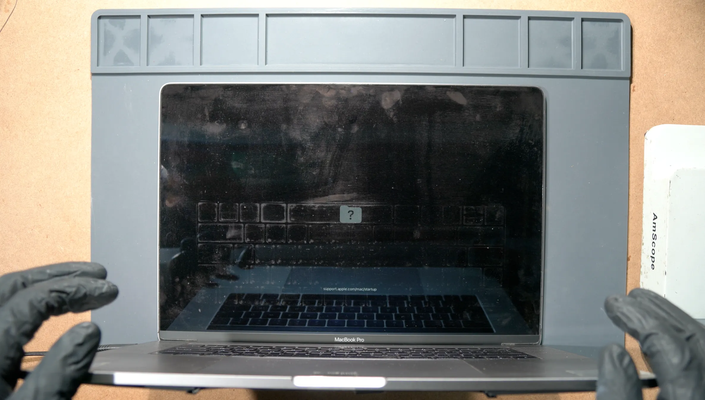
This MacBook came in with no SSD issue, boots straight up to Question Mark Folder.
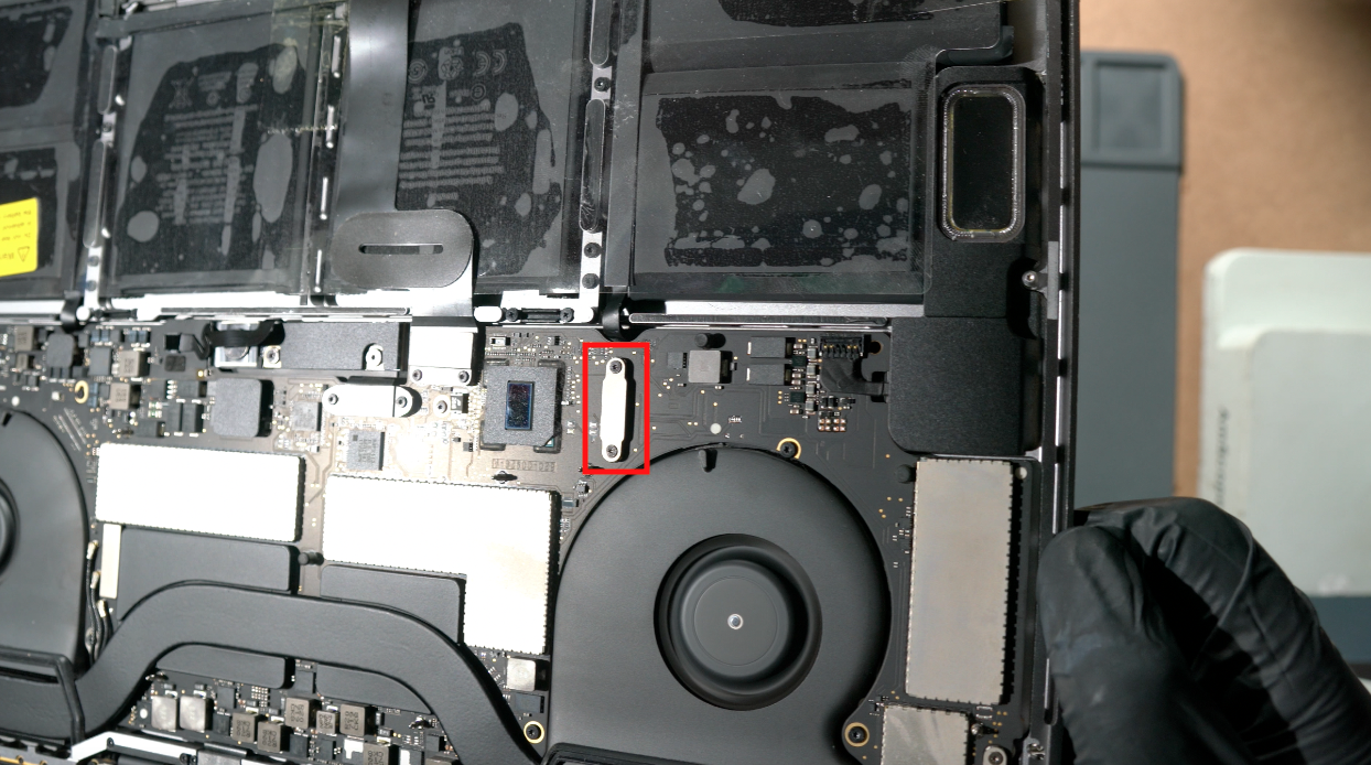
Make sure the lifeboat connector is properly plugged in all the time.
Booting into Recovery doesnt show any sign of internal SSD presence.(only Recovery Volume found)
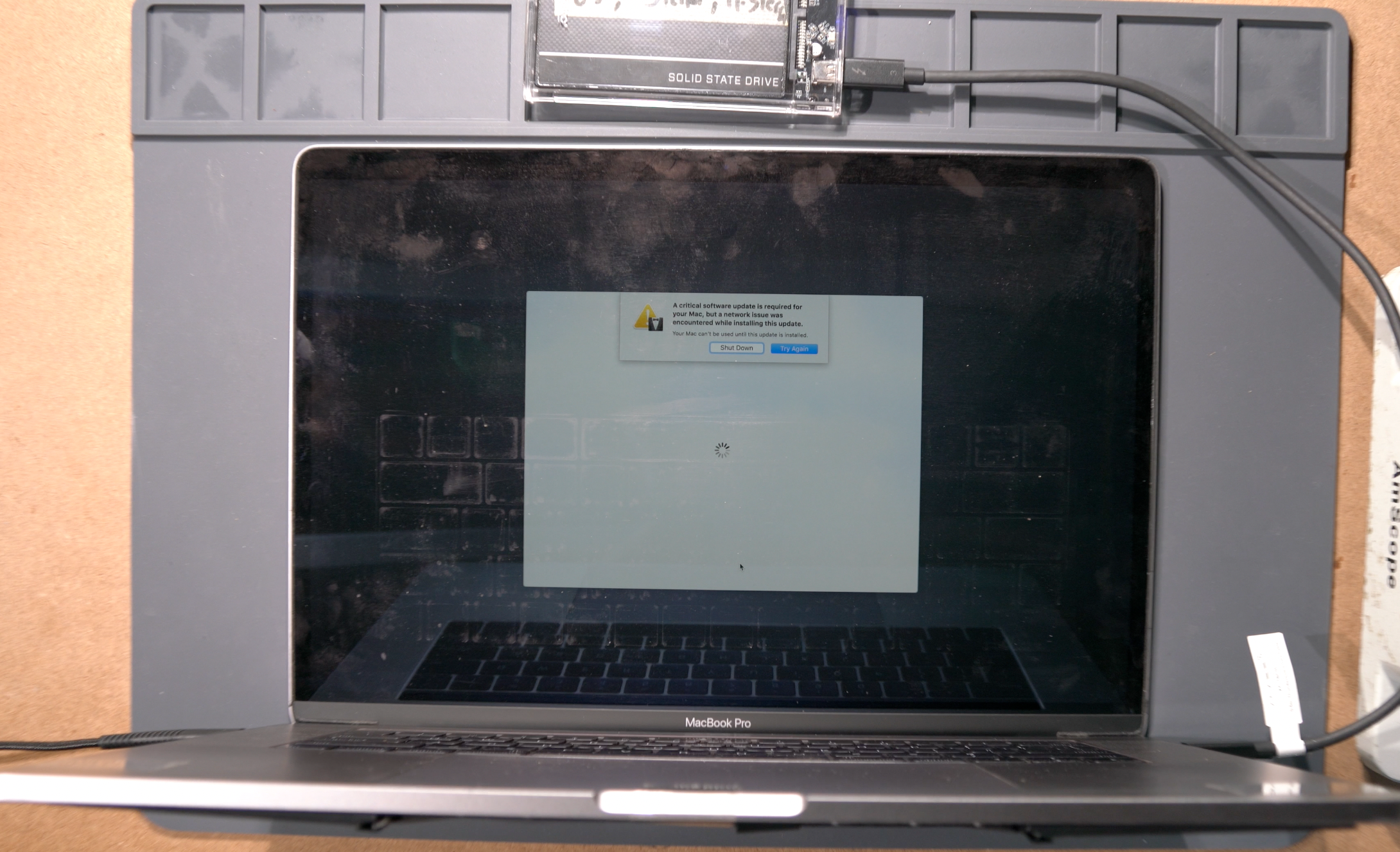
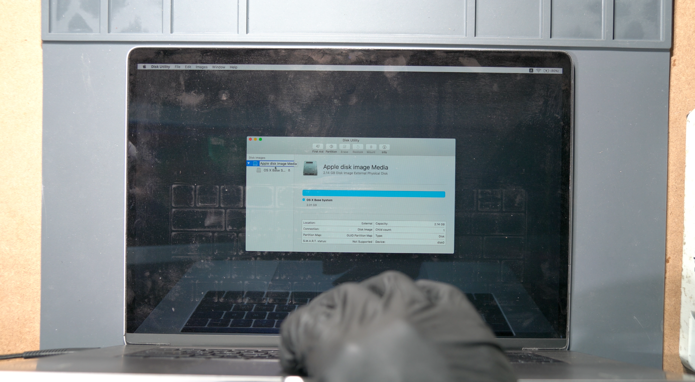
You can try to boot external MacOS using external drive, but you will end up with "Critical Software Update" prompt. This is the sign of missing T1 partition inside the onboard SSD. We will call this T1 Partition as "T1 Critical Software Update" for now. More about this at the end of this guide. So, when you are having this kind of SSD issue(only for T1 Mac), its either:
1. The NANDs/Controller are dead
2. Voltage SSD supply issue
3. The Lifeboat connector is not connected properly
4. Shorted caps, etc
We dont really care which one is it, because this A1707 NVMe adapter will solve all of them once.
SOLDERING STAGE:
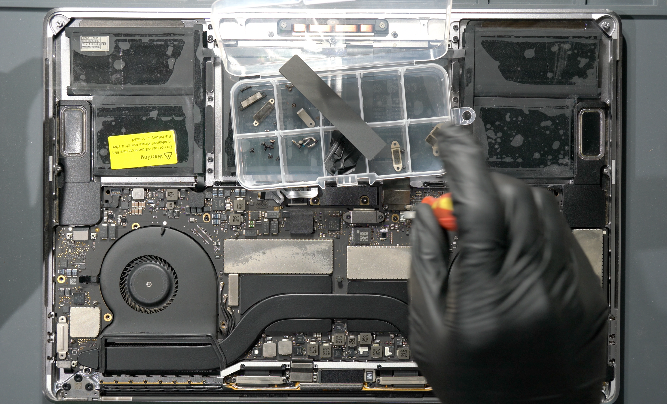
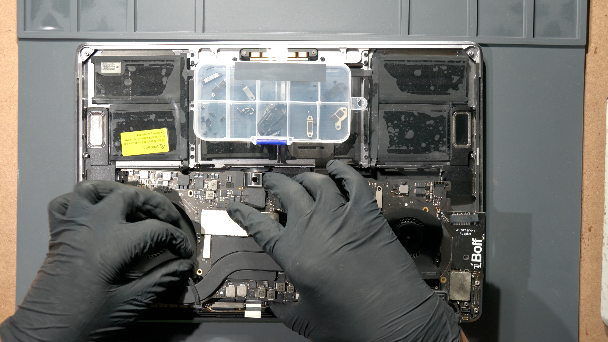
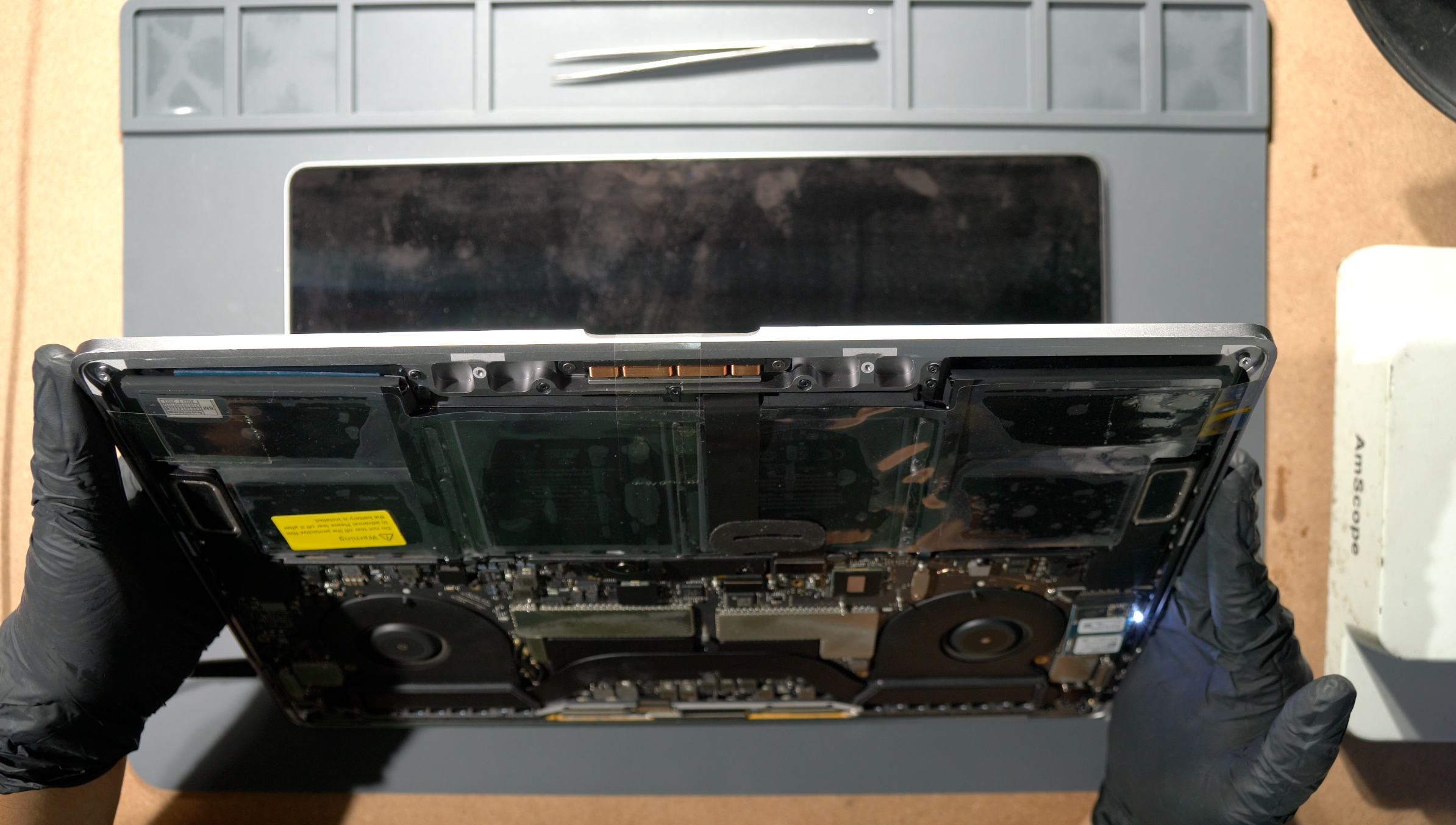
Disassemble the whole MacBook to get access to the MLB.
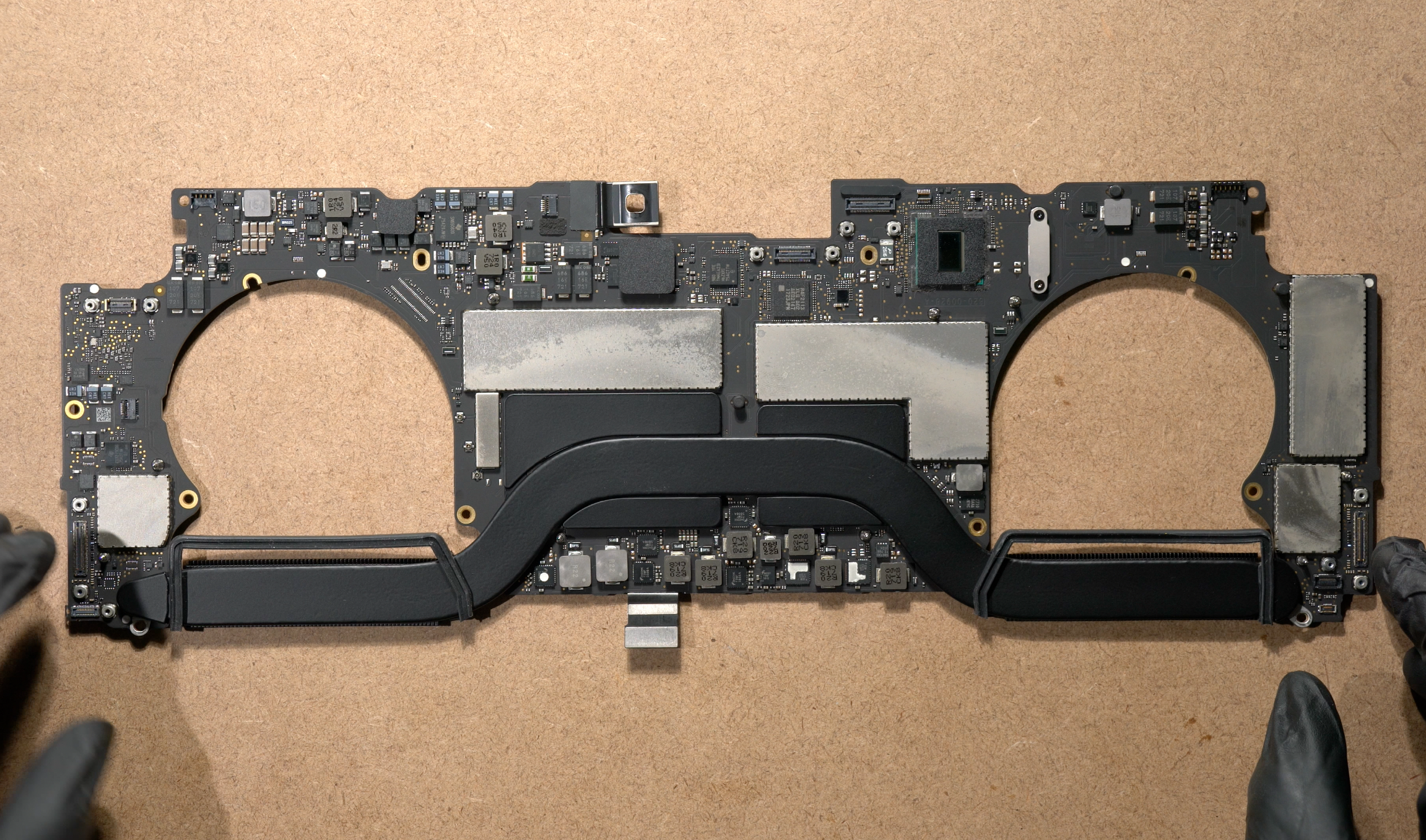
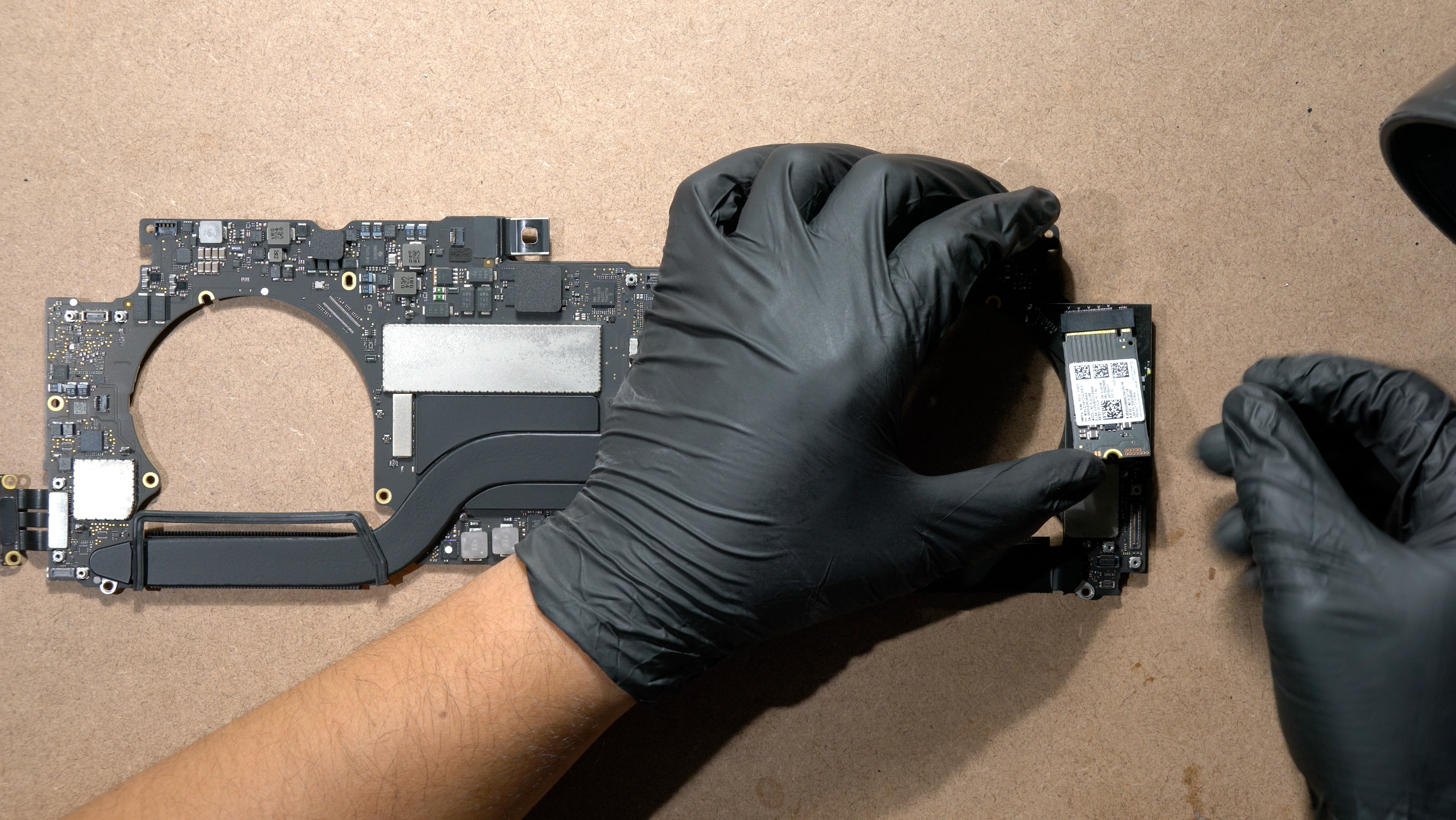
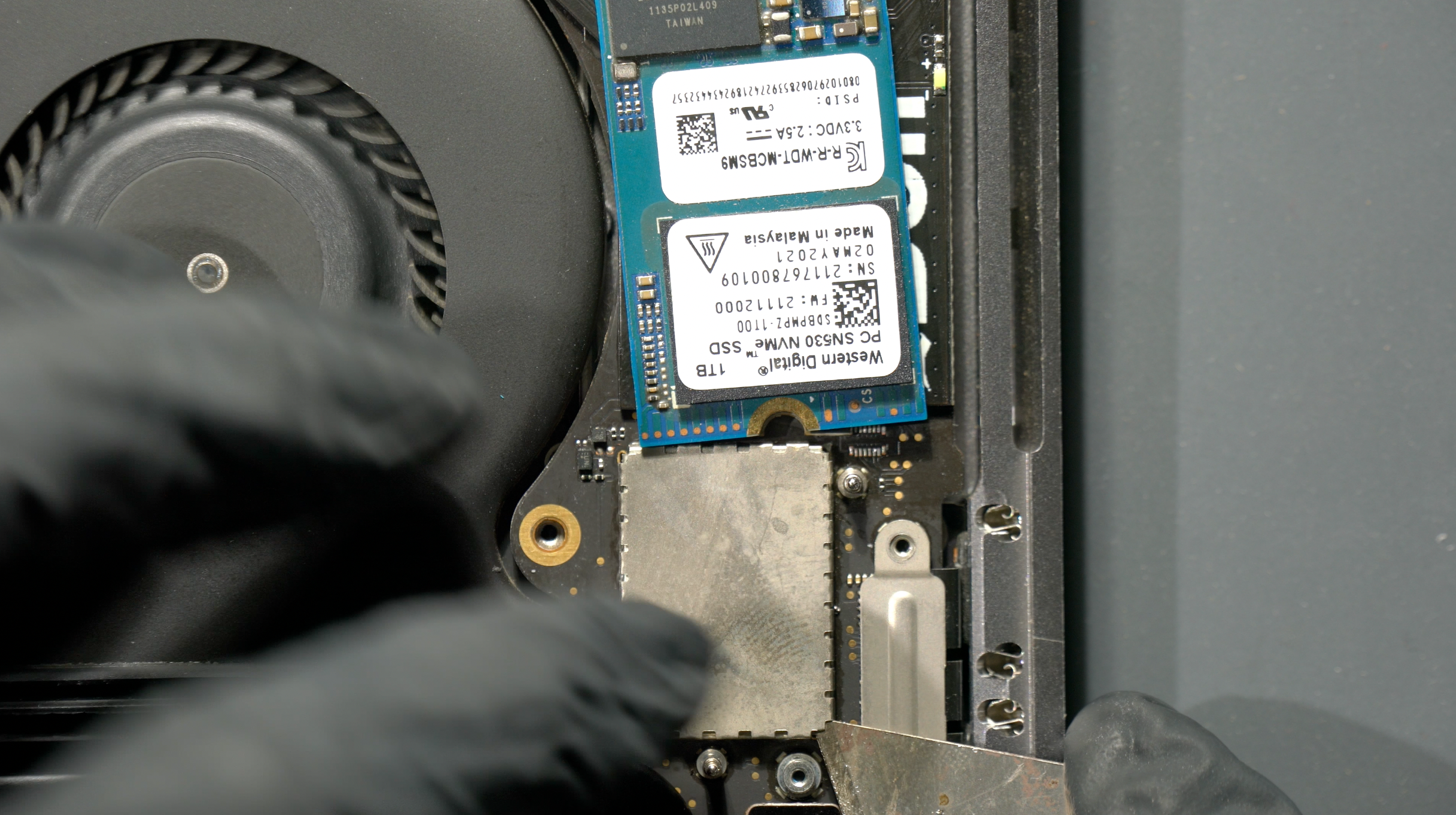
MLB safely removed from the chassis, focus to the SSD area on the right.
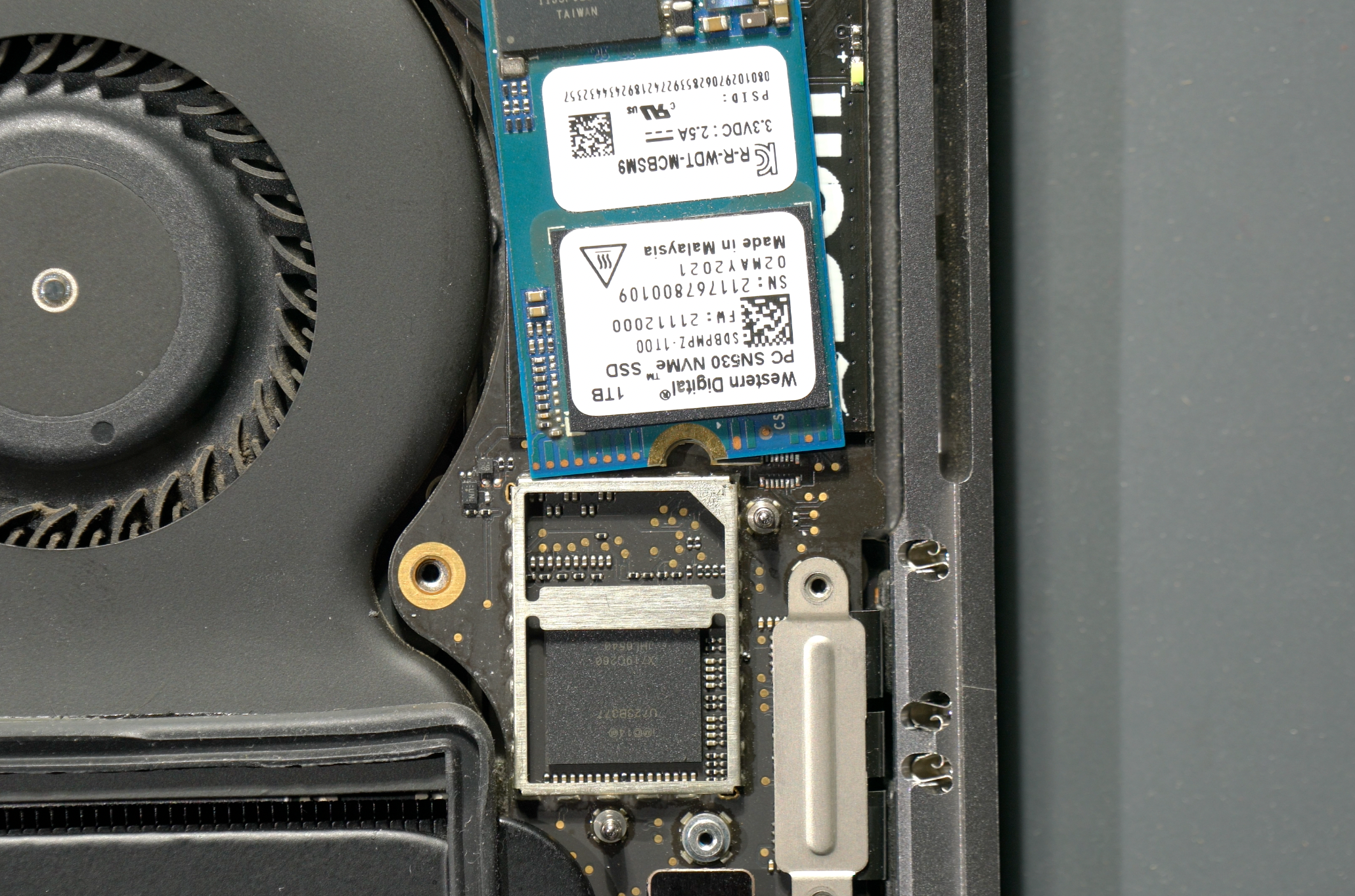
Pry off the EMI metal shield covering the NANDs and controller. 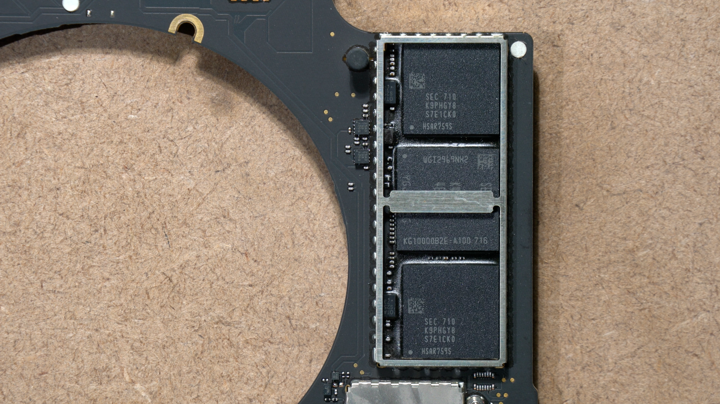 Exposed NANDs and SSD controller(center)
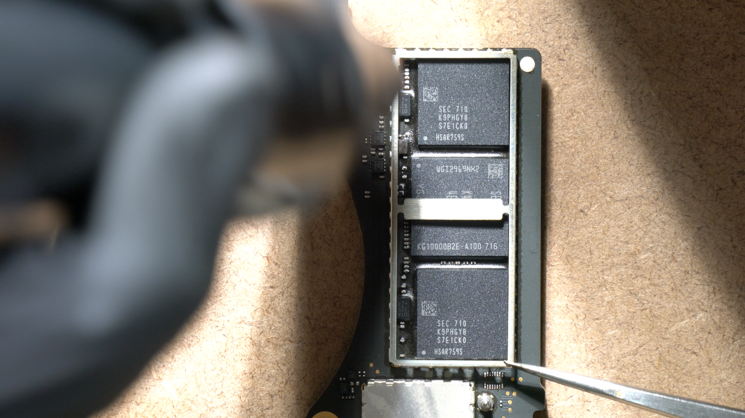
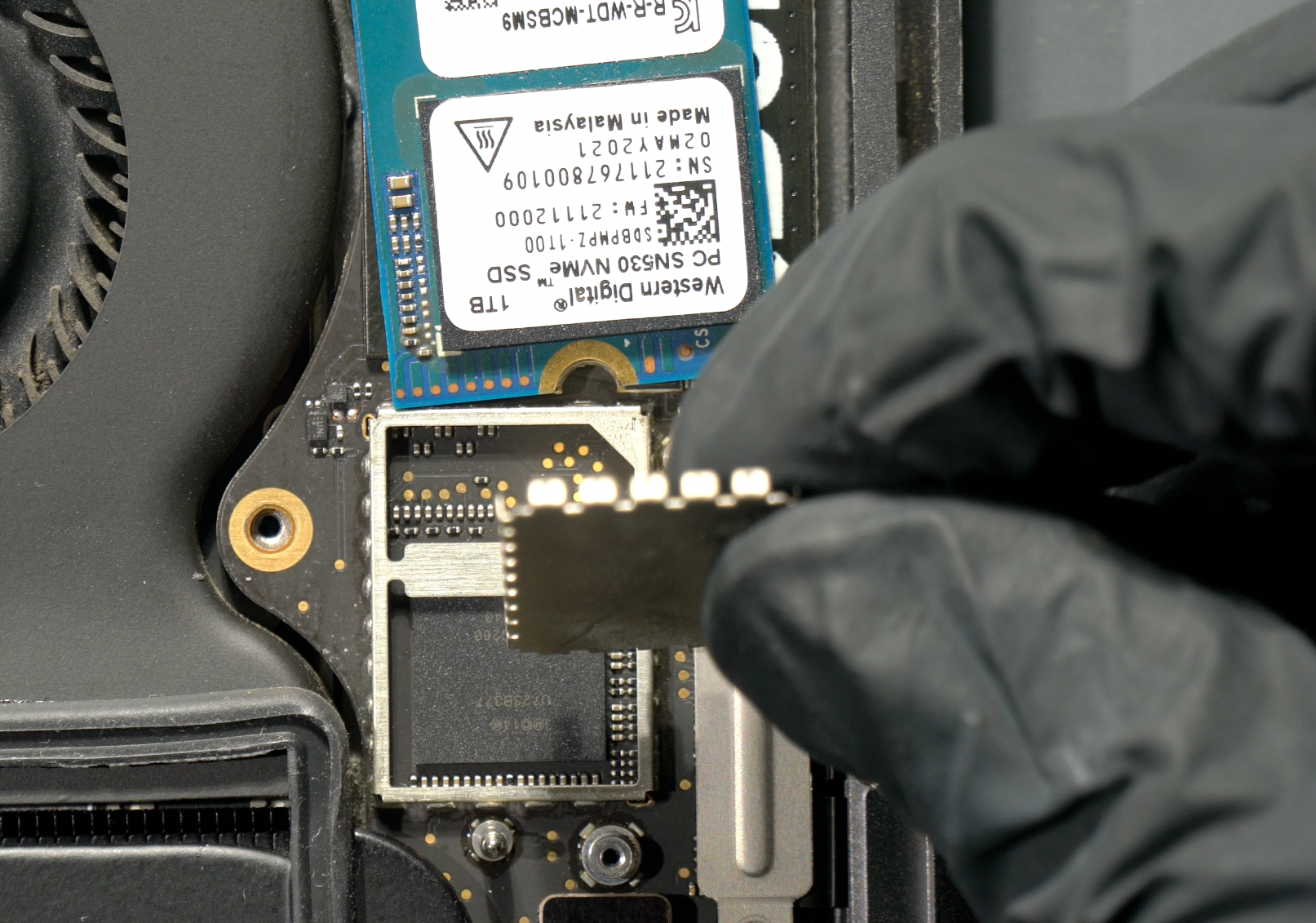
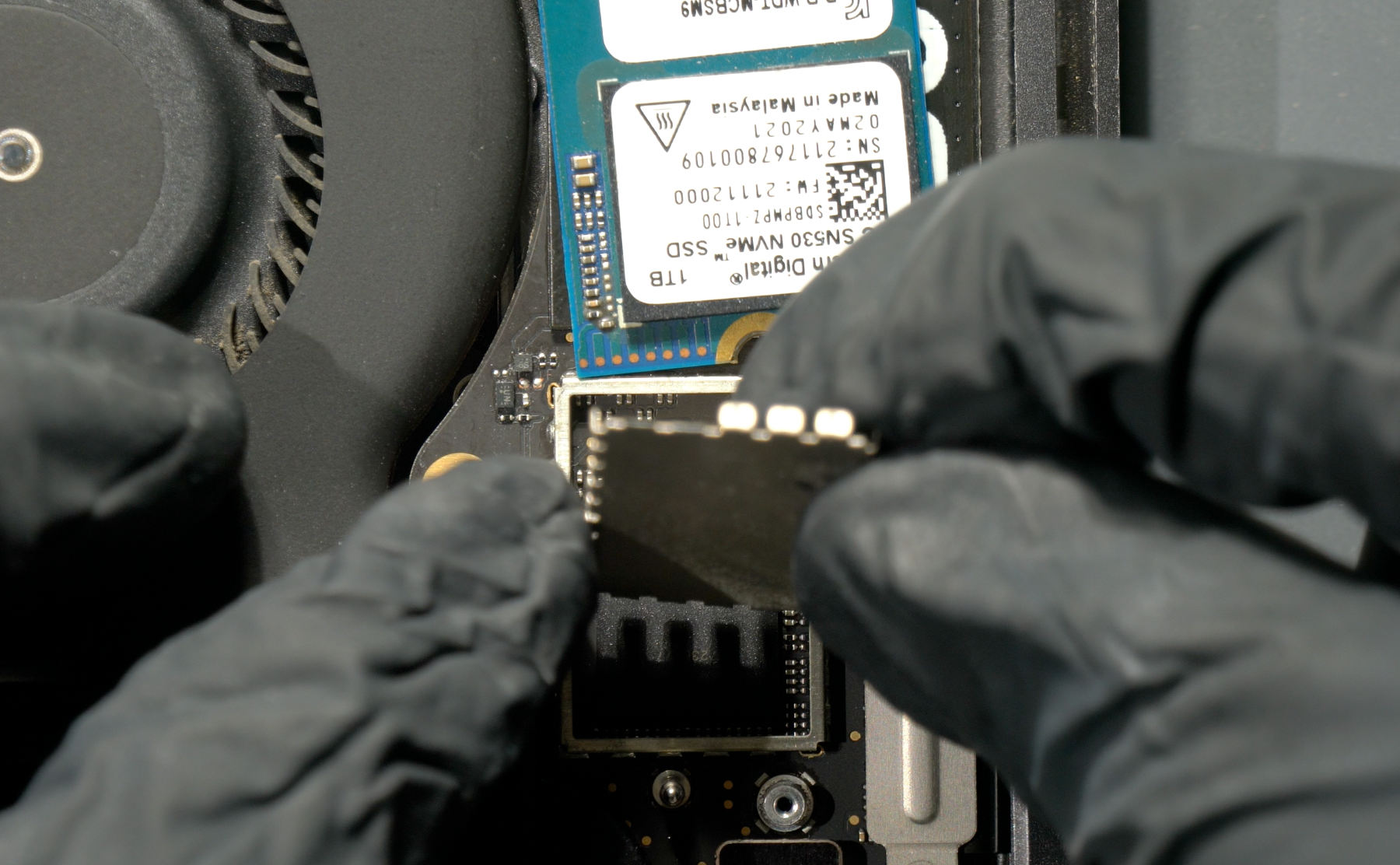
Begin to remove the metal guard around the SSD using hot air gun(no nozzle). Circulate the hot air around the local area until it reach liquidus lead-free temperature(poke any SSD caps to guess the timing) and slowly lift the guard.
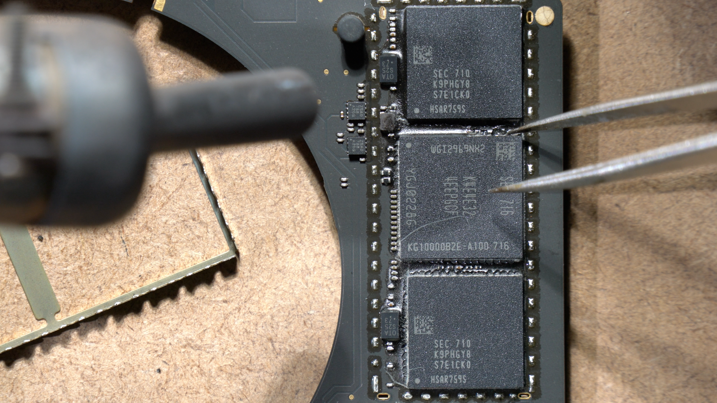
Remove the black underfill around the NANDs & controller's perimeter for easier BGA lifting later on.
Surrounding black epoxy removed, local SSD circuits and ICs dont matter anymore.
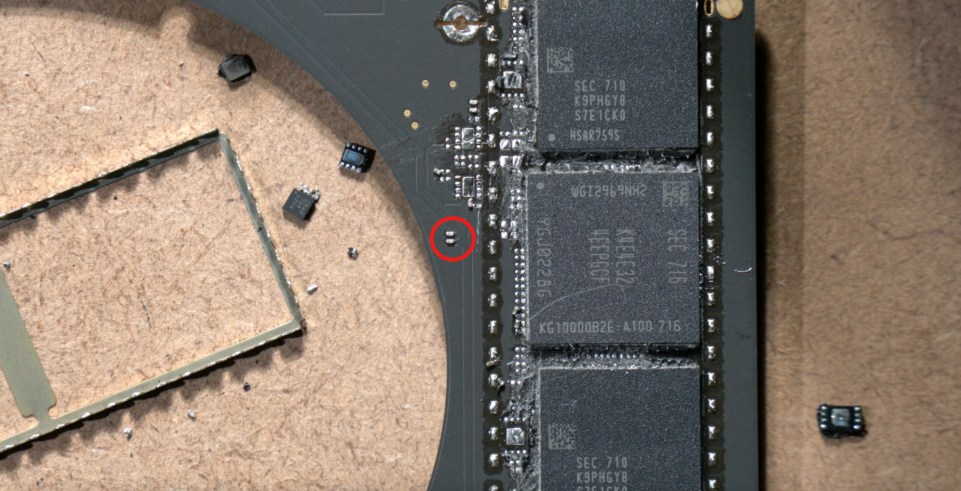
Watchout for these two caps, it belongs to other circuit so please dont remove them. (CC754 & CC755)
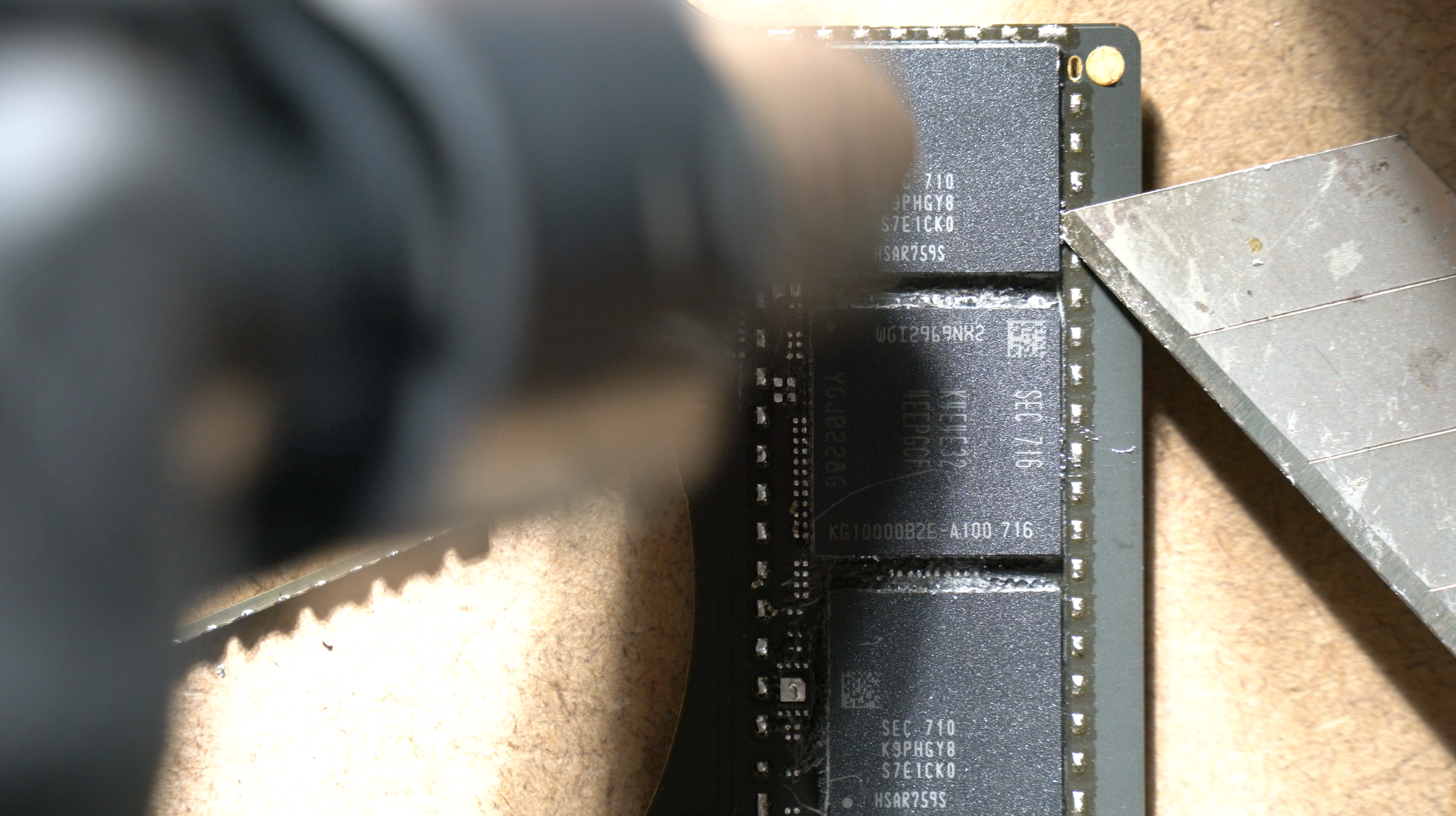
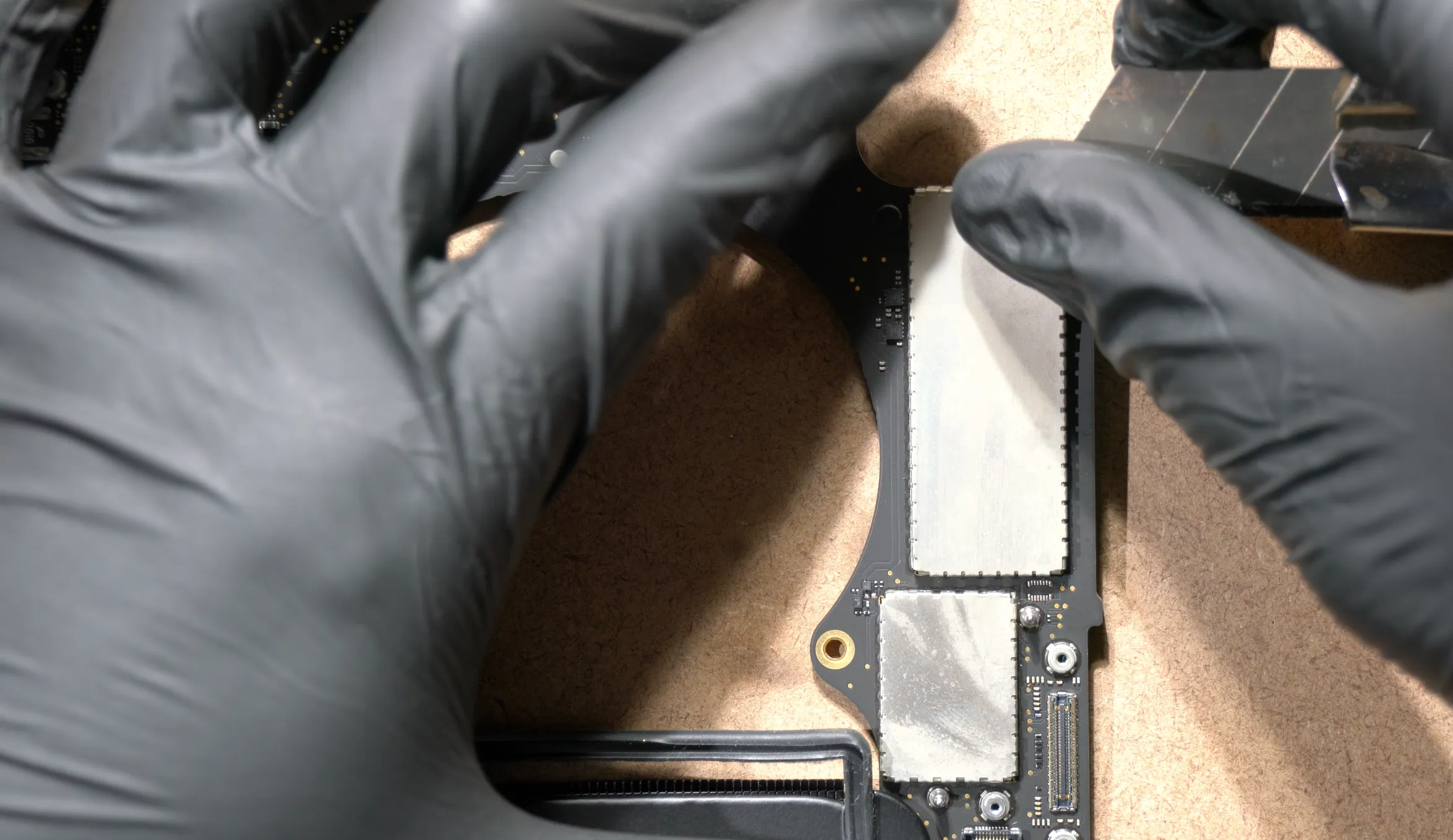
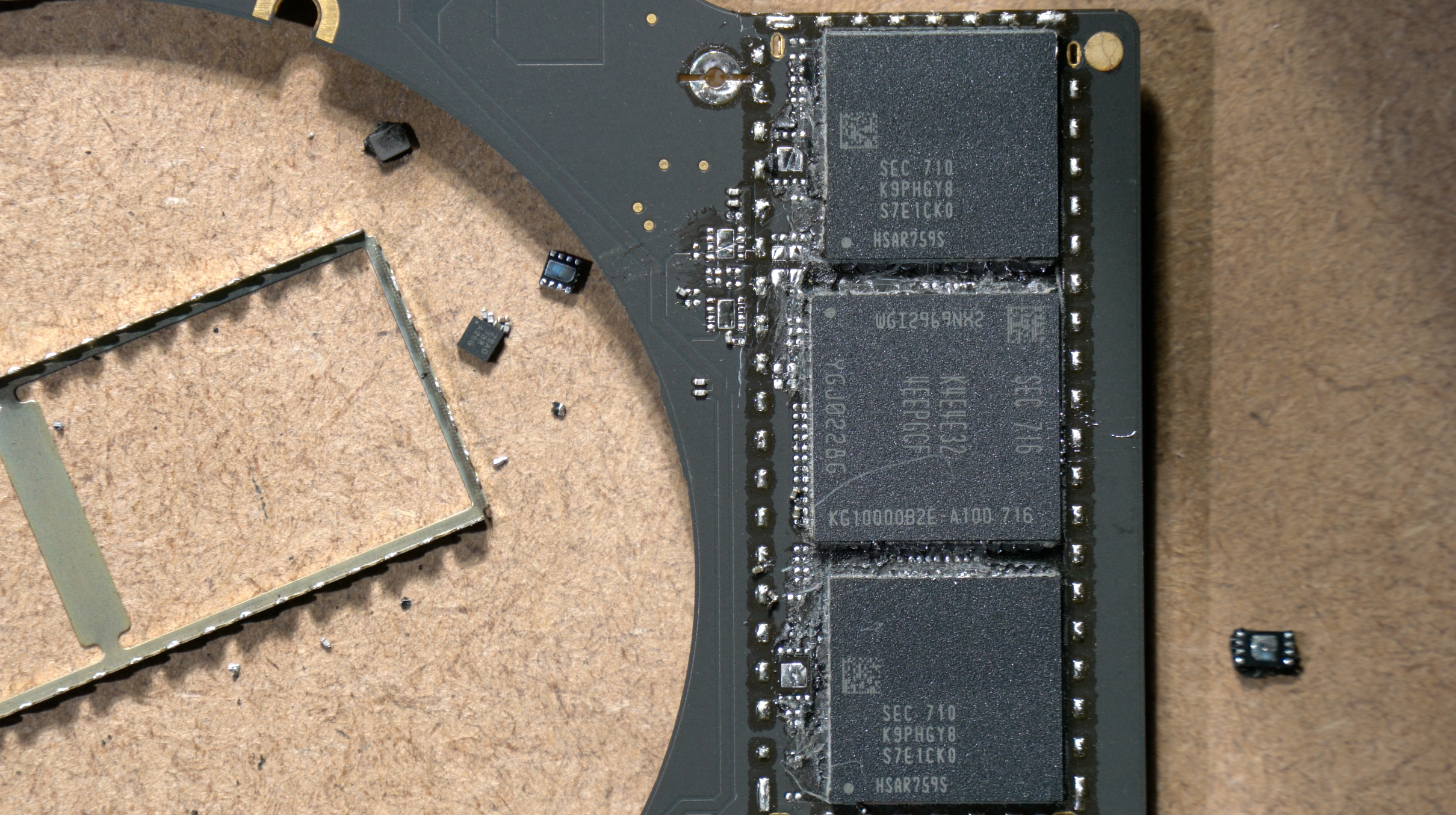
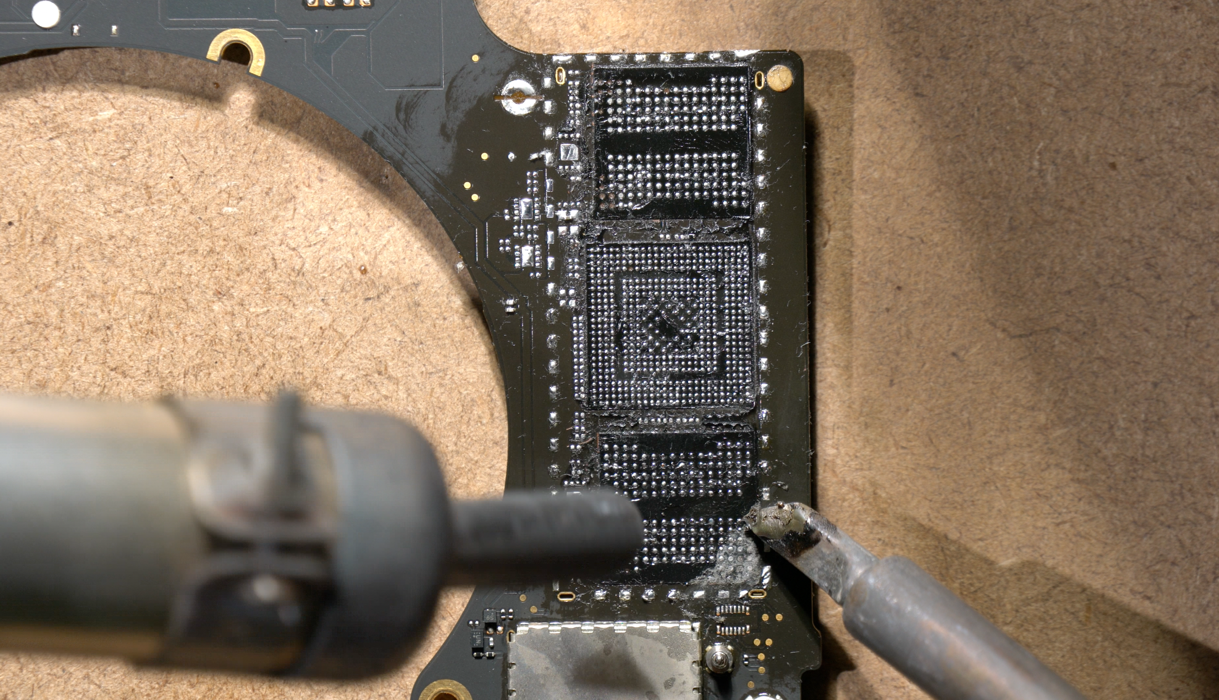
Start to heat the right wing again with the hot air gun(no nozzle) and begin to remove the NANDs and controller using knife. Make sure the temperature reach lead-free liquidus temperature to minimize solder pad loss.
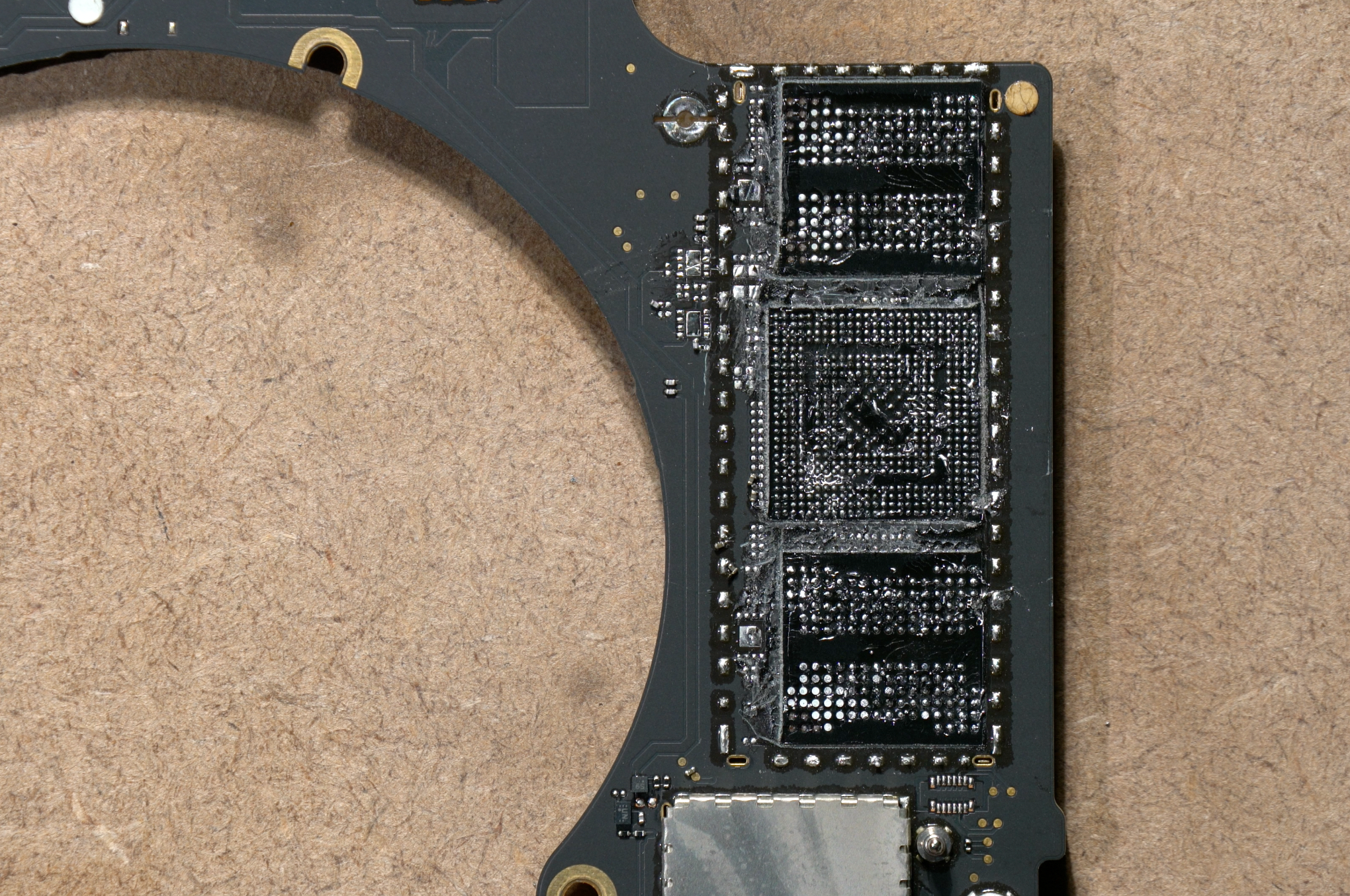
All SSD components safely removed.
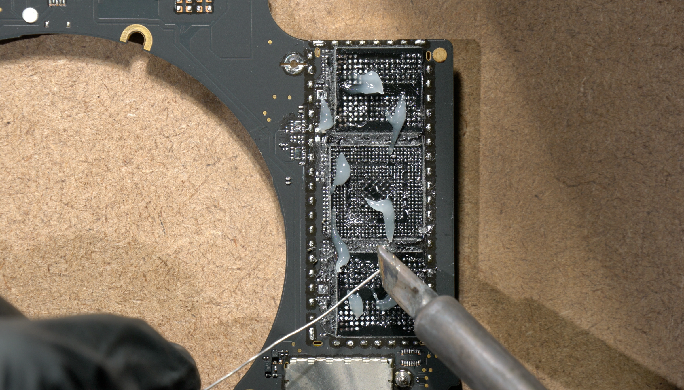
Apply flux and run the pads with leaded solder wire.
Begin to scrape the remaining underfill on the surface using the solder iron aided with hot air gun(if you have better removal method then do it)
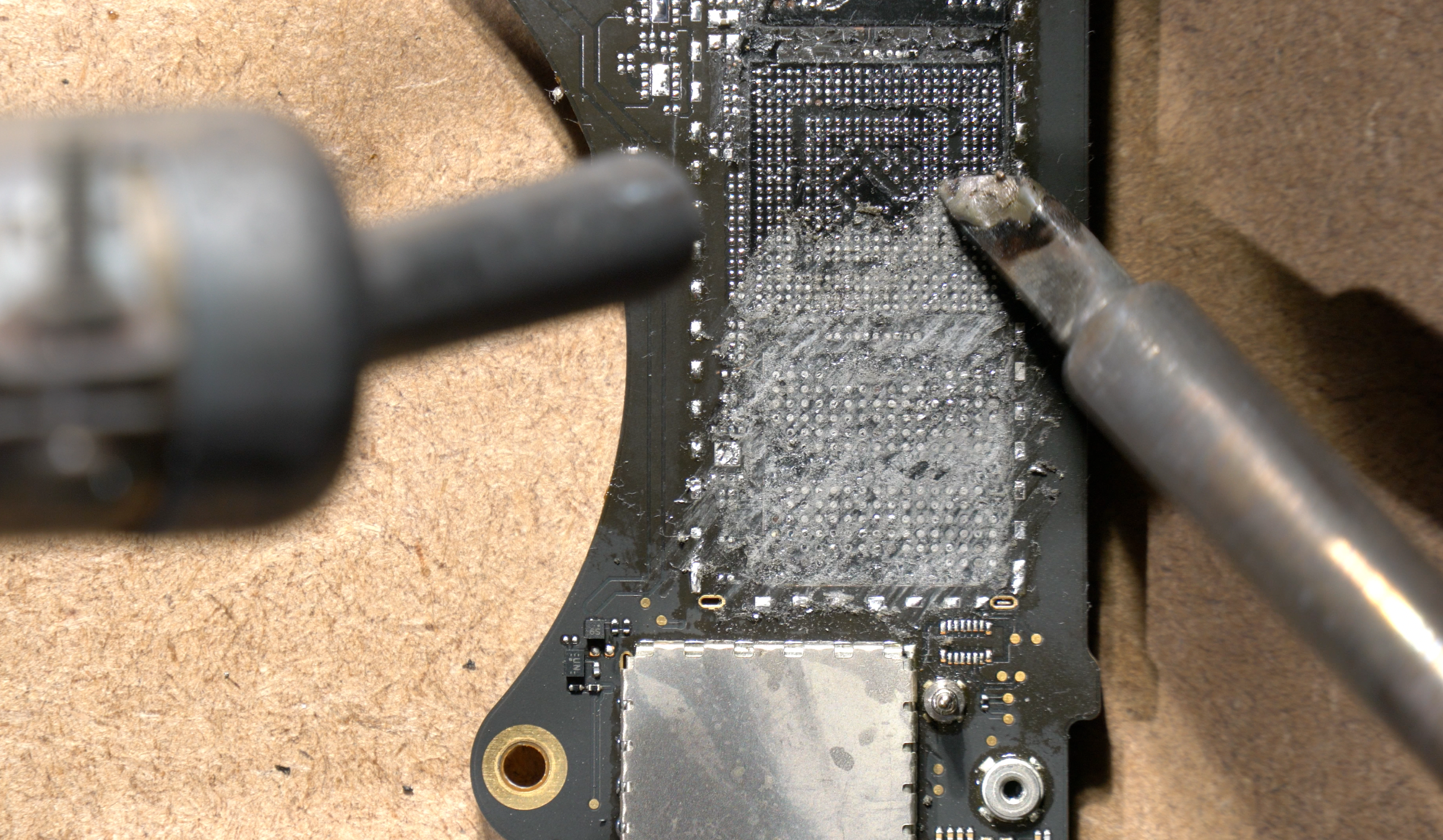
Almost there...
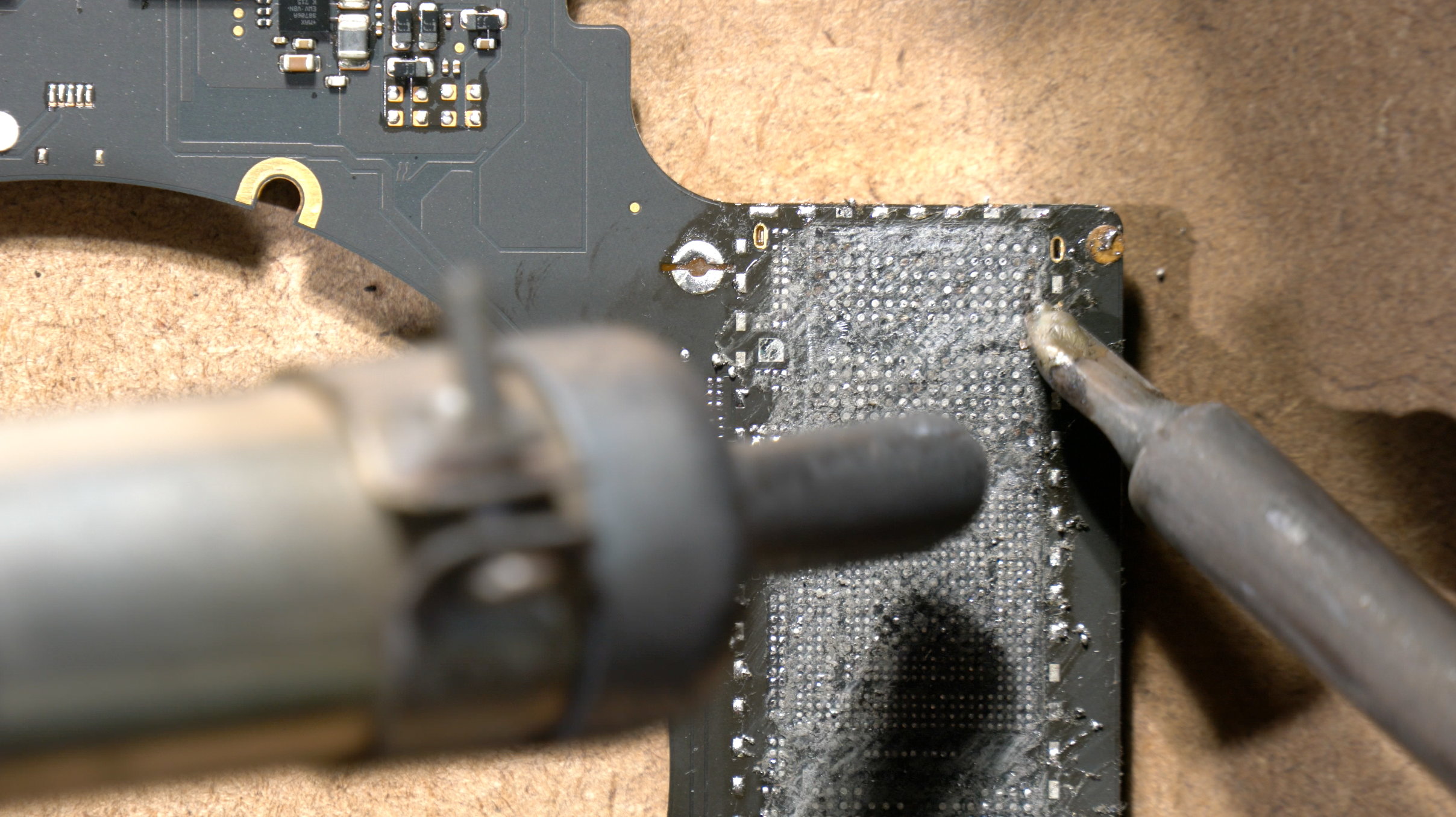
All underfills have been removed.
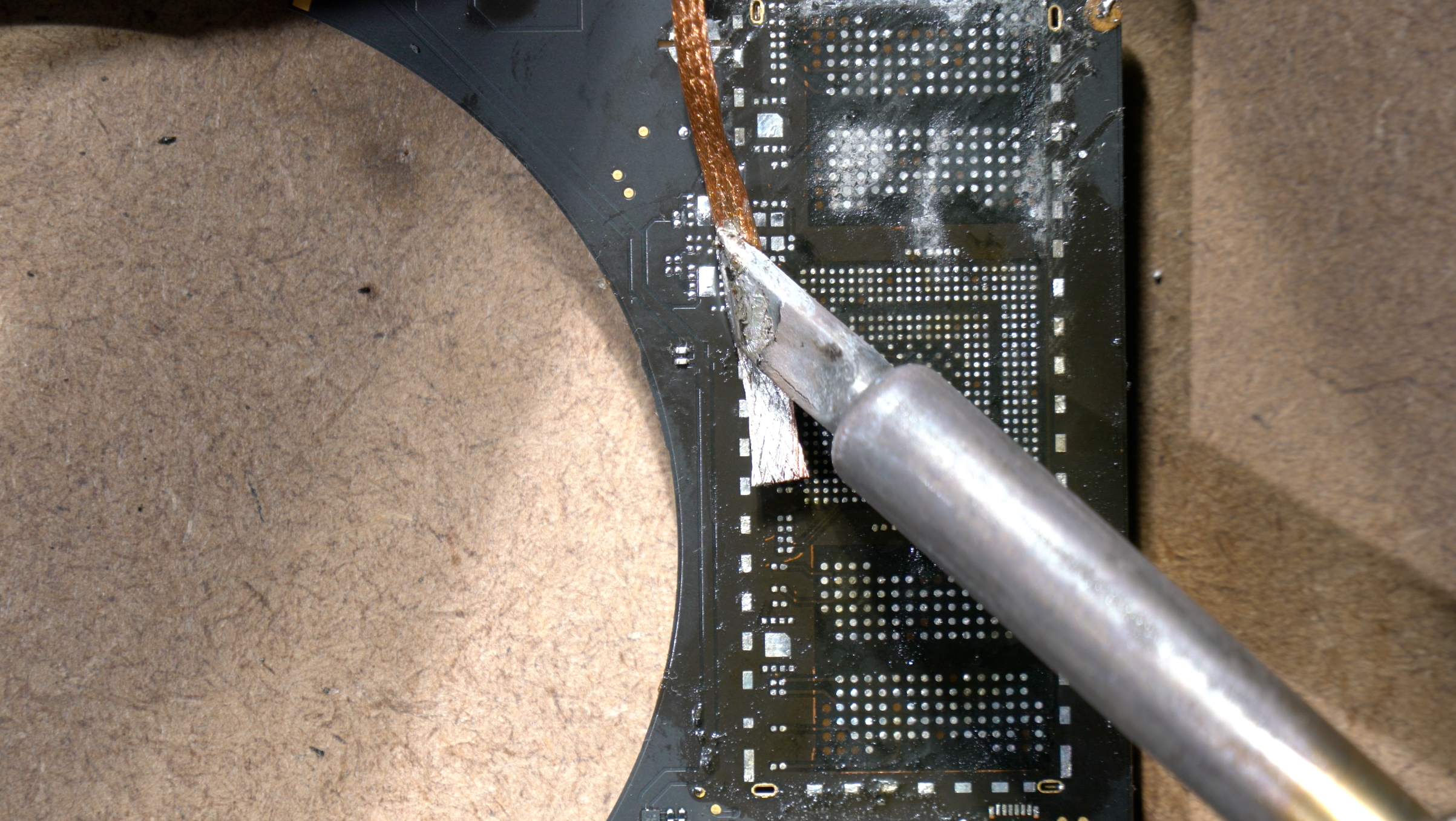
Remove the remaining solder on the surface using wick & flux.
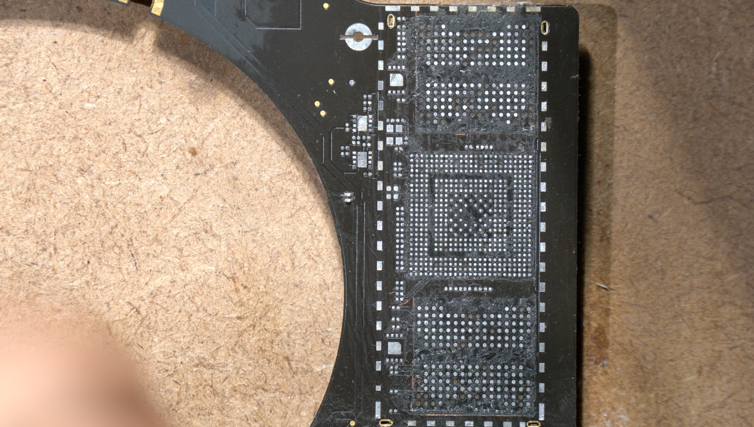
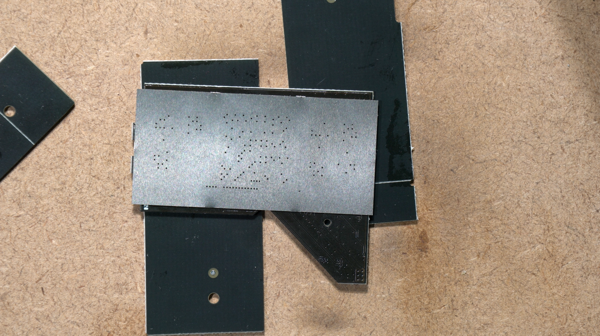
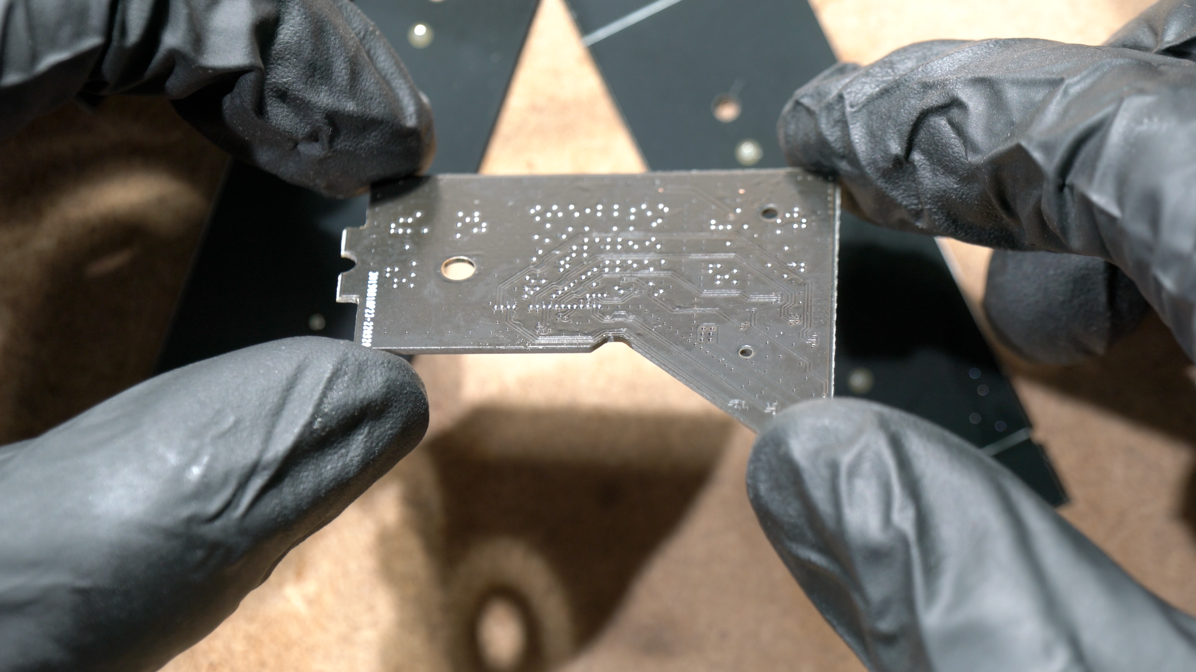
This is how it looks like after completing underfill removal. You can see some solder pads are missing, and I know some of you can do better than this. But its not really an issue because the critical testpoints are only as follows:
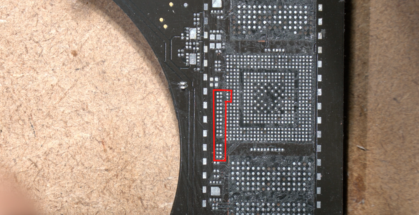
You MUST NOT lose the pads in the red lines.
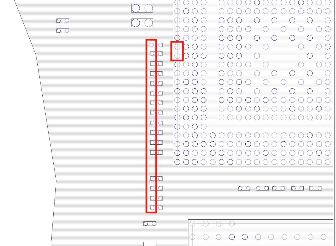
They are PCIE_SSD_R2D <0-3> , PCIE_SSD_D2R <0-3>, and PCIE_CLK100M_SSD.
You can measure their diode values and it should be around 0.2-0.4 , MAKE SURE they're not shorted or OL. These values are coming from the PCH.
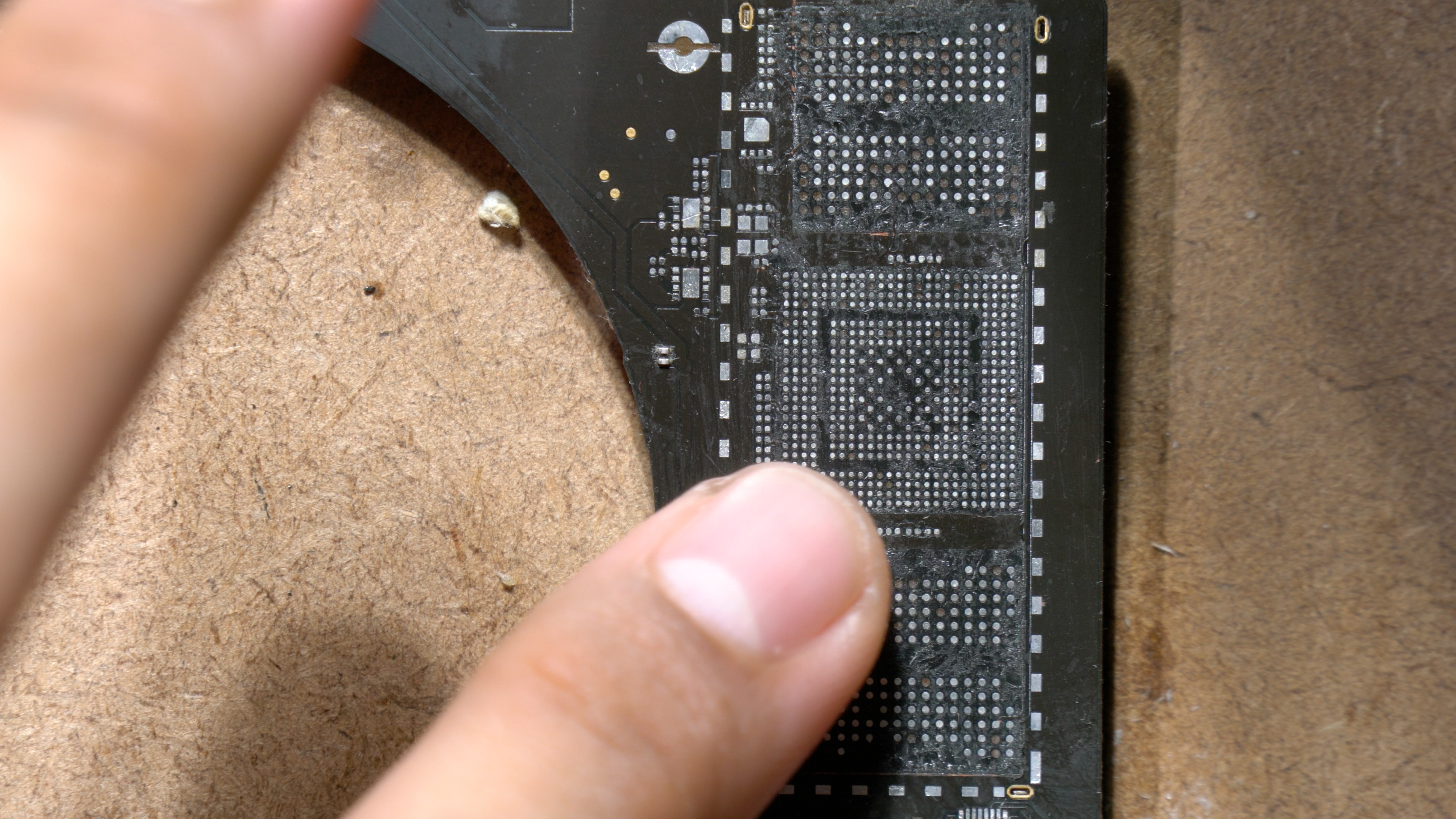
So now, "PROFESSIONALLY" feel it with your fingers to make sure all underfills are gone. You have to make sure the surface is flat and smooth. Im not kidding, it has to be real flat and smooth, because the balls youre going to use on the A1707 adapter is only 0.3mm size.
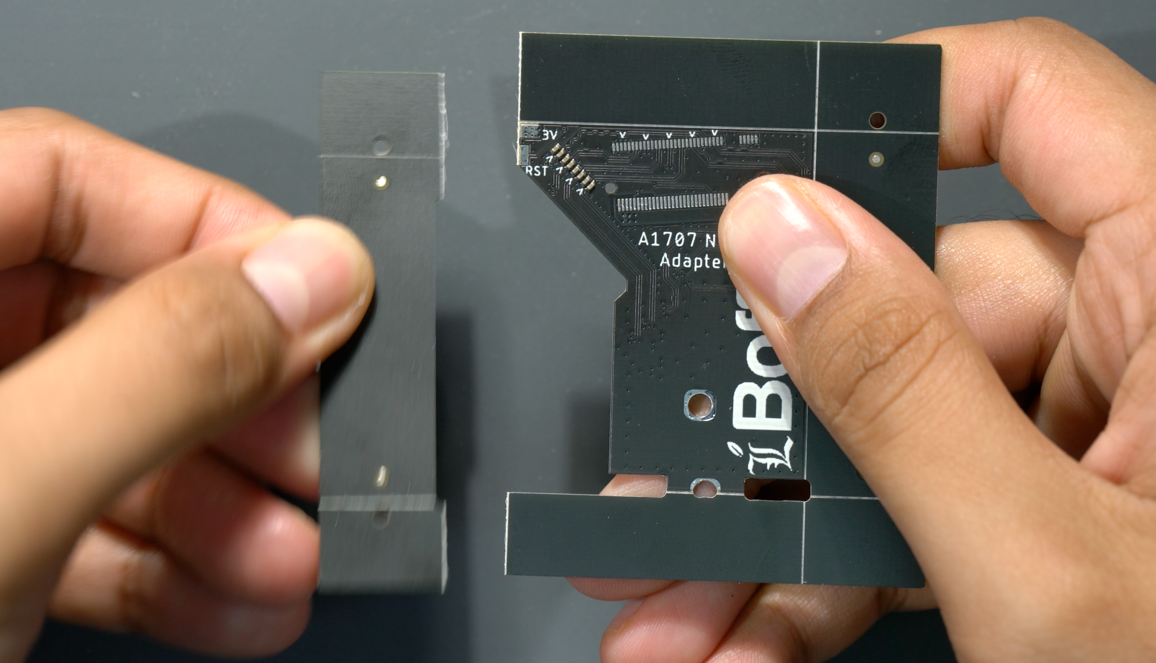
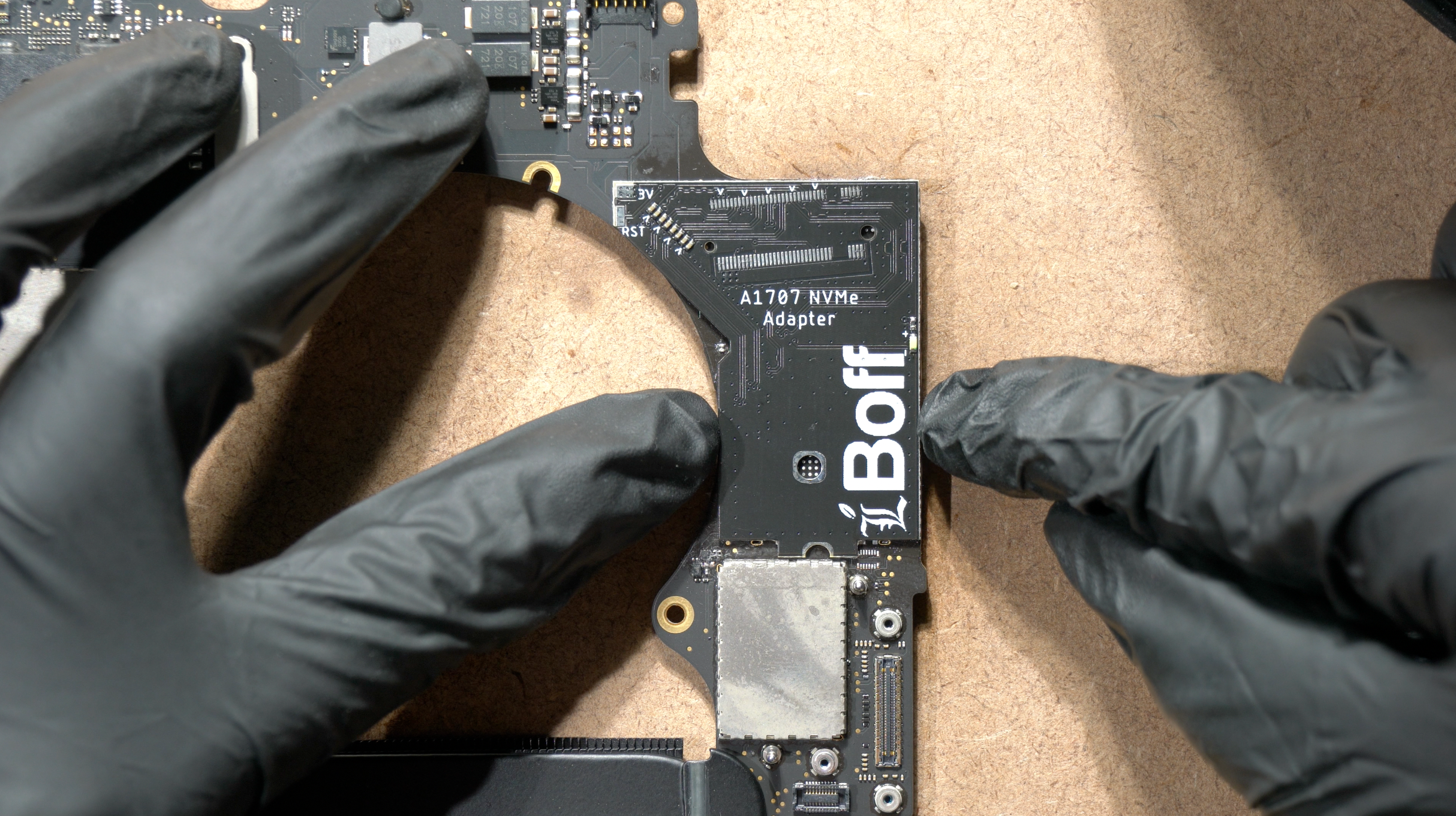
Unbox the A1707 NVMe Adapter like you did for your Gundam Kit.
As you try to lay the adapter on the MLB, you should feel no obstruction or bulging on the surface.
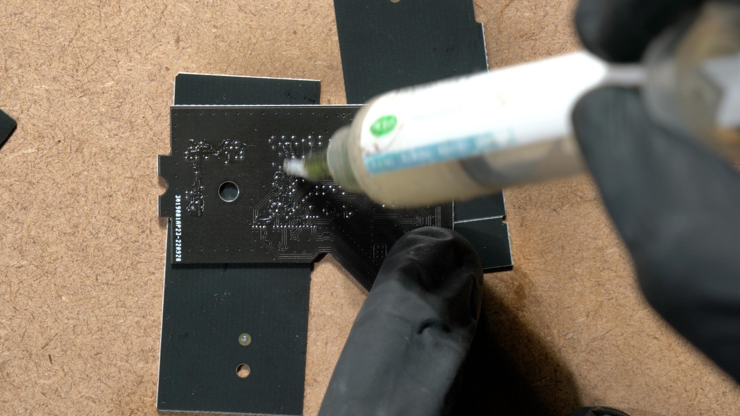
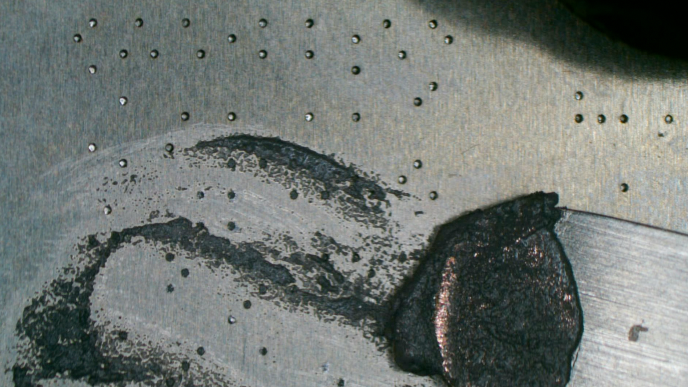
Apply flux if you want to reball using 0.3mm balls.
Use the stencil provided to reball the solder balls.
Another option would be reballing with solder paste.
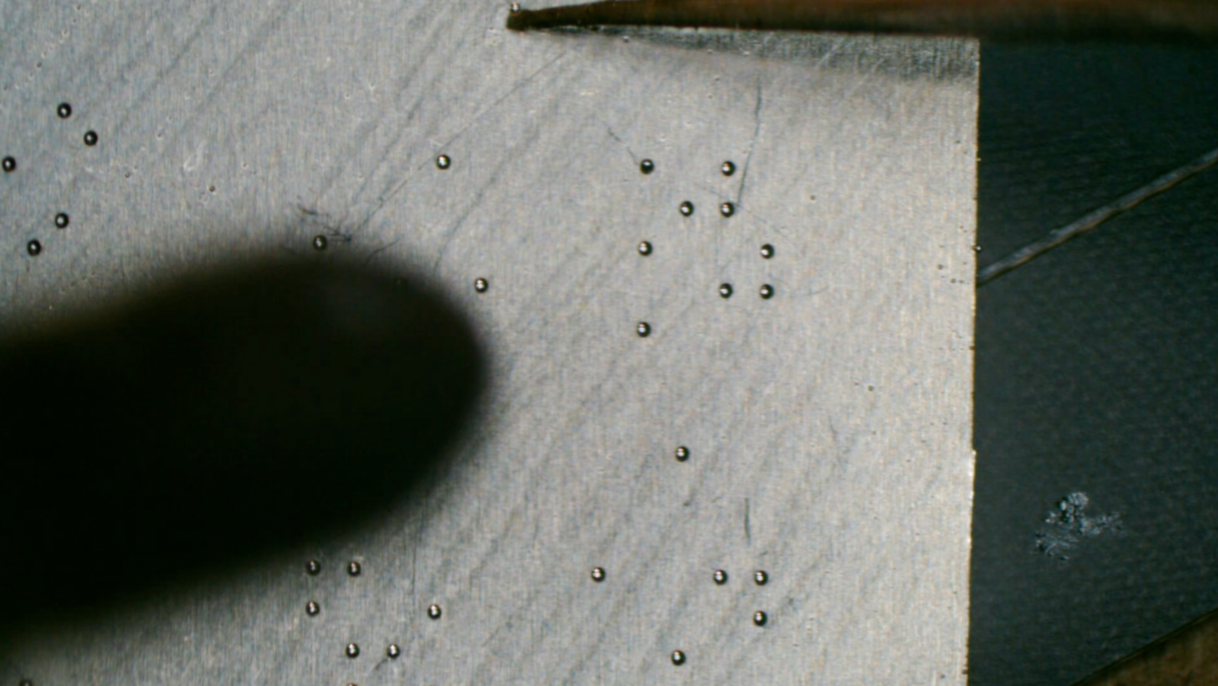
Heat it with hot air gun.
Successfully reballed with paste, give it a bit of reflow
These are the balls for the PCIE_R2D, PCIE_D2R, & PCIE_CLK100M. They are the most critical you need to check, as other balls are just for GND and PCB support(but you need to make sure GND balls are sufficient enough for return current).
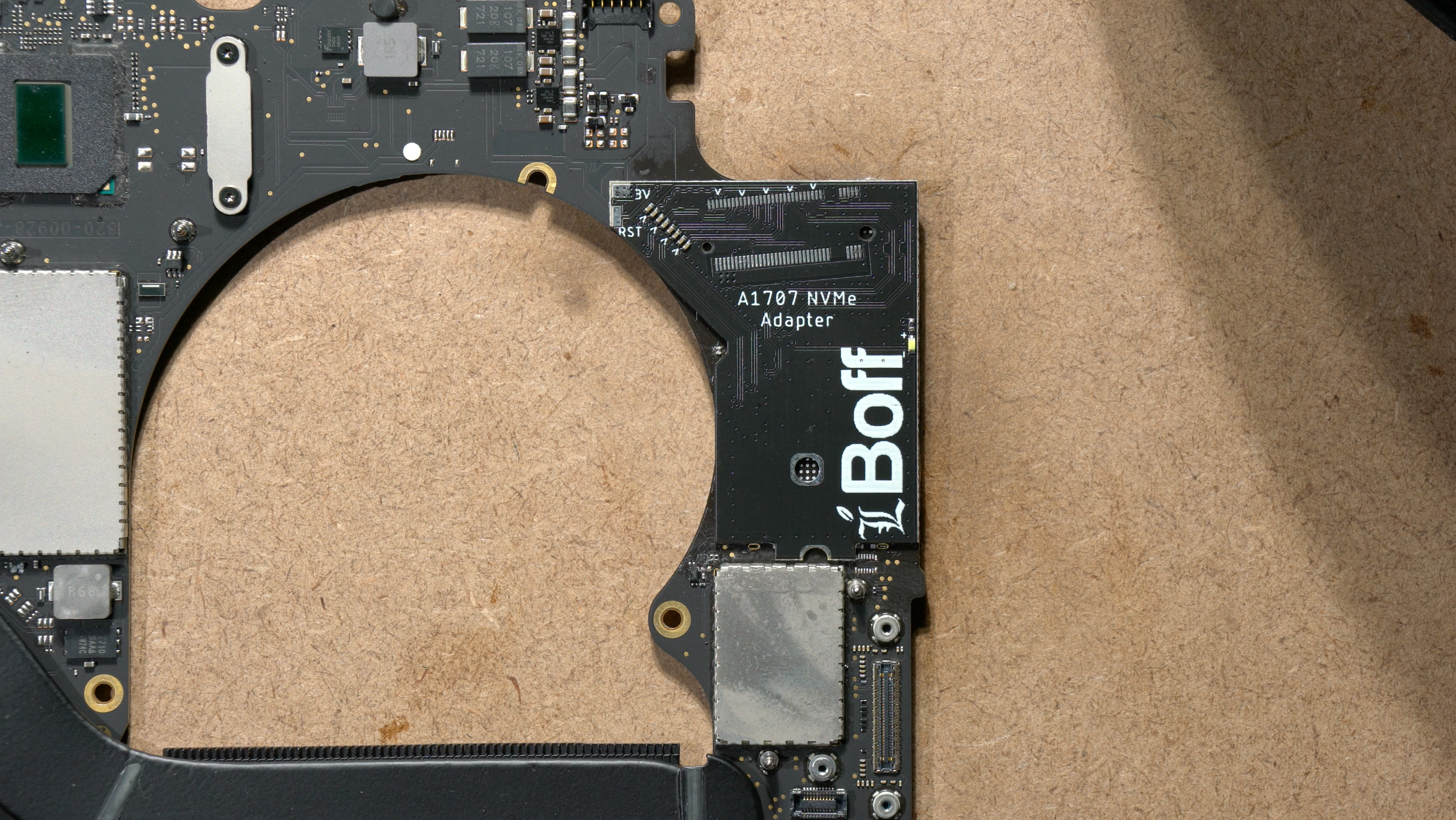
Take the reballed A1707 adapter and place it to the MLB
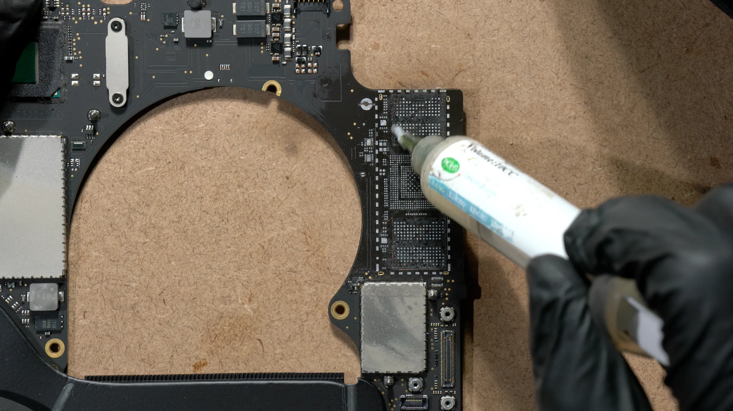
Apply flux to the MLB surface,
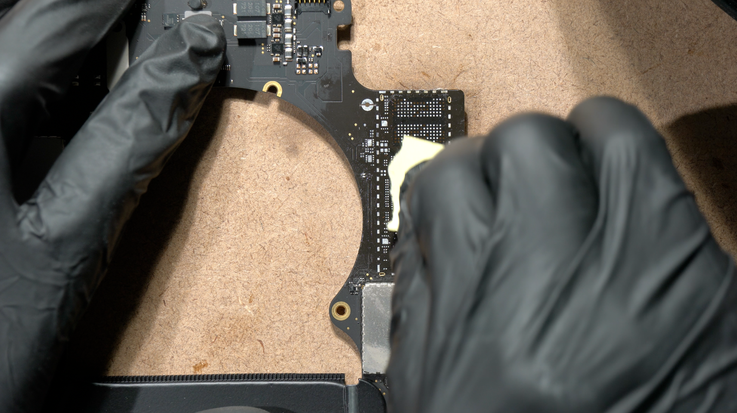
Spread it out to make it really thin layer of flux.
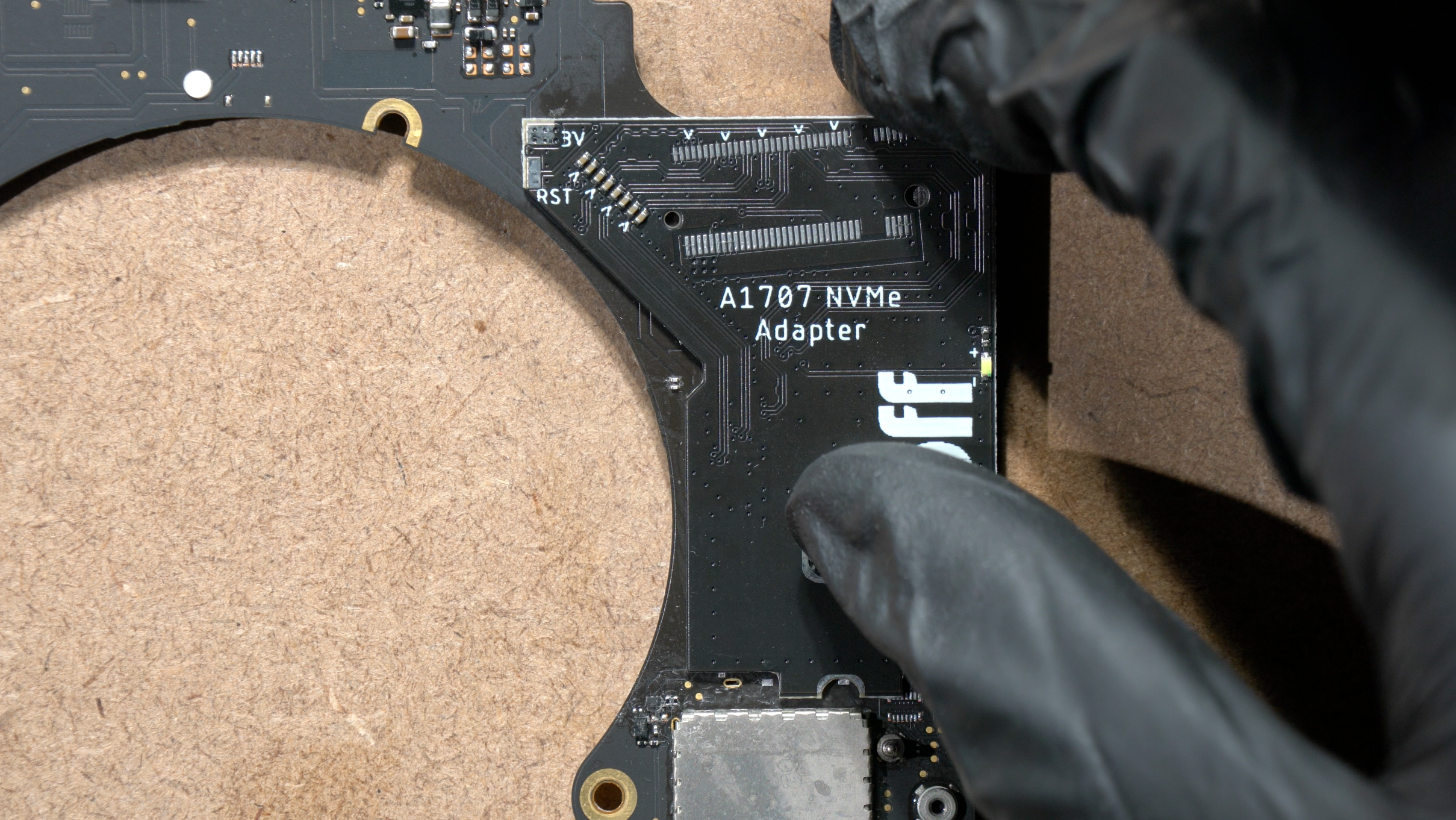
Align the adapter into place,
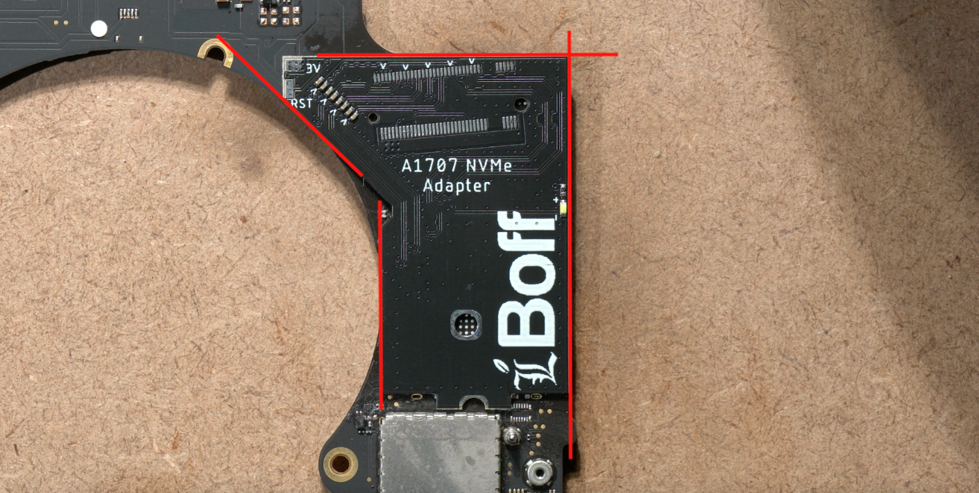 Align the adapter following these 4 lines. Basically you have to align it matching the edges of the MLB.
The A1707 adapter was designed to perfectly match the MLB dimension with the PCIe functional pads.
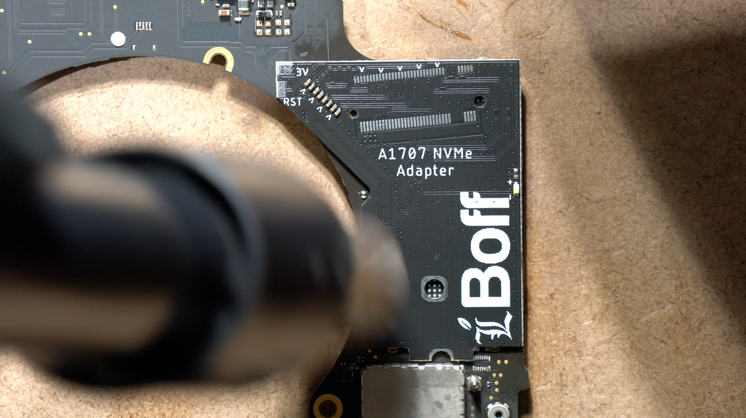
Heat it with the hot air gun(in circle, no nozzle) until reaching leaded liquidus temperature.
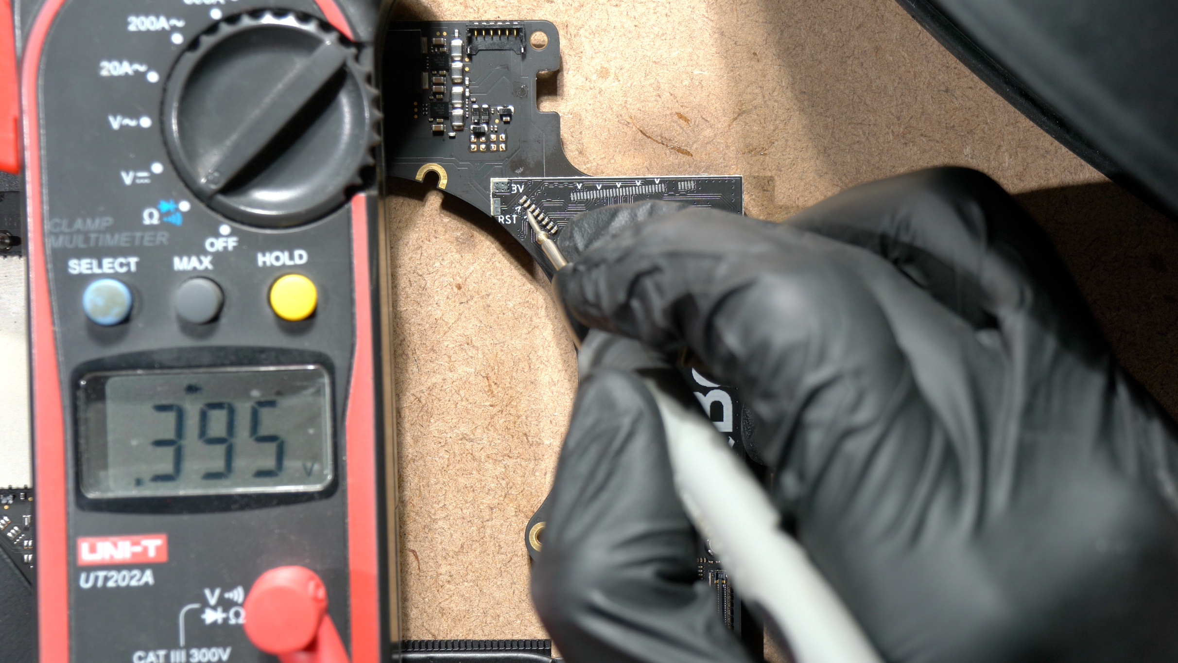
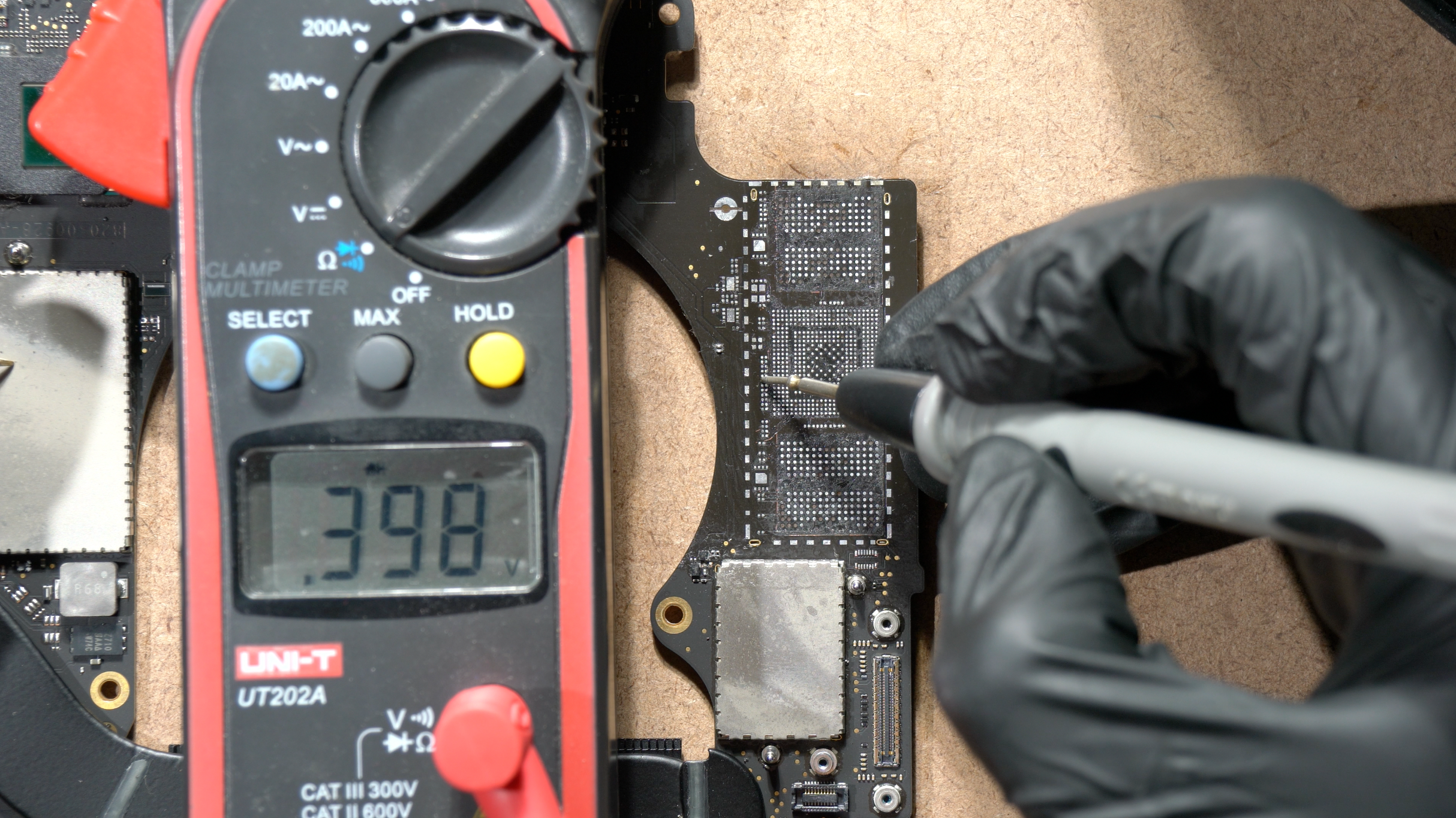
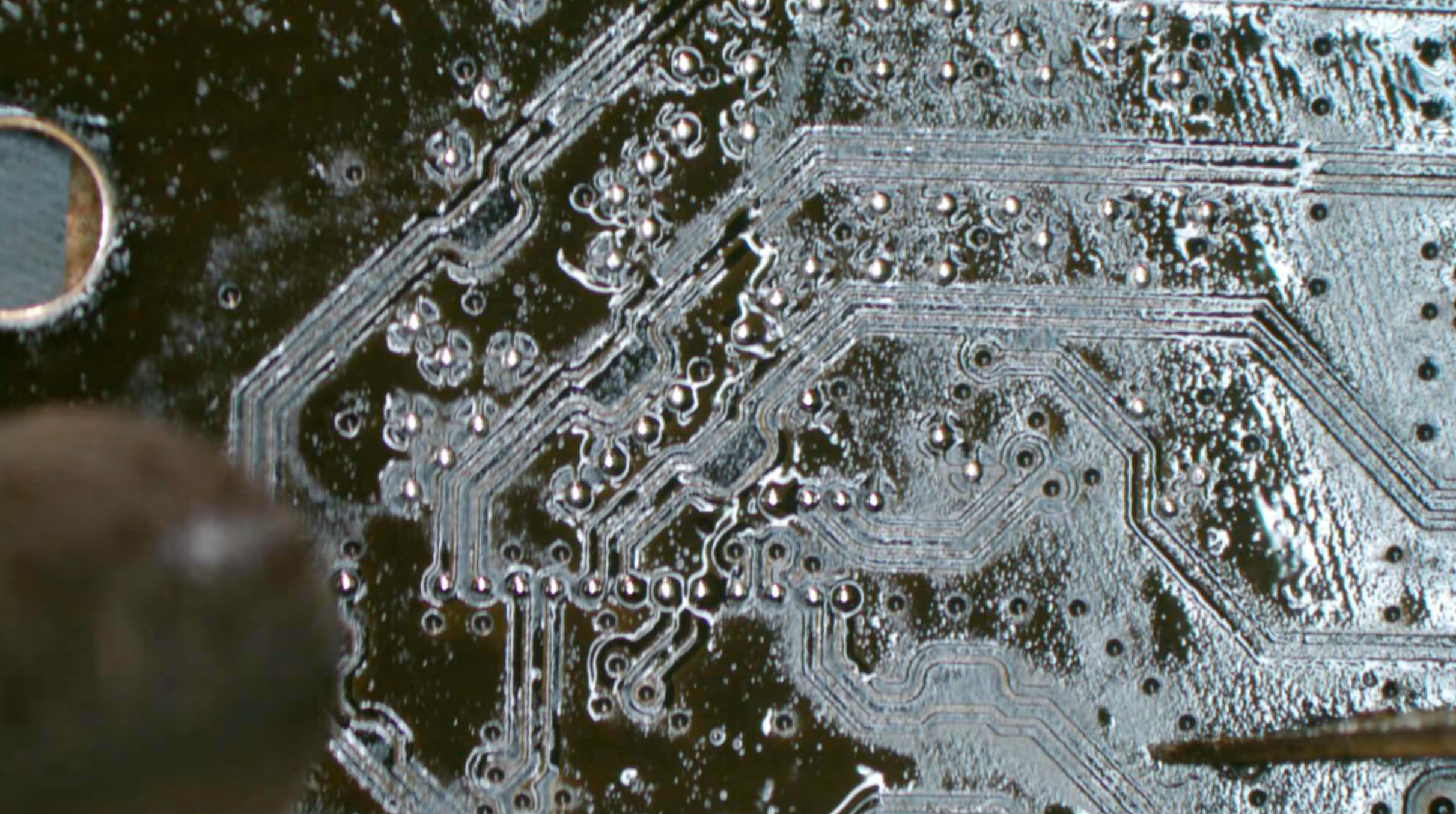
Measure the testpoints on the A1707 adapter, they were marked as small arrow. For an arrow, there will be a differential pair = 2 copper traces = 2 diode values close to each other. This is to ensure the solder balls fall correctly on all testpoints, & to make sure the joints integrity are established after soldering. (picture above: measuring on caps)
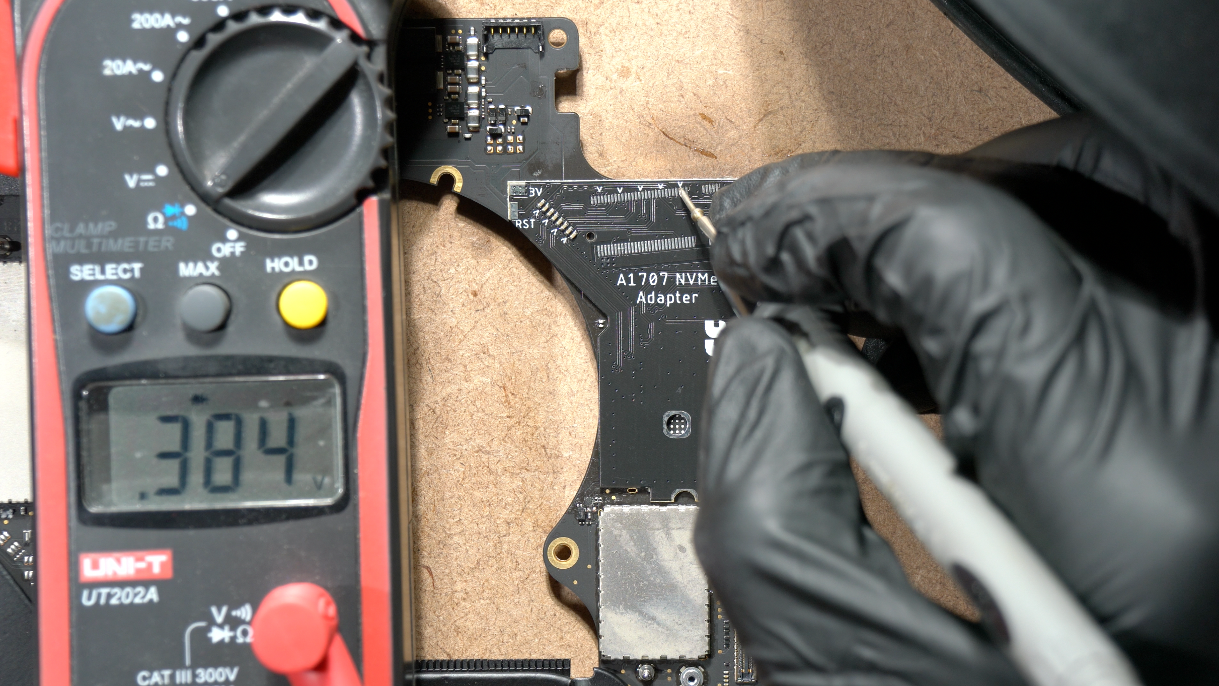
Picture above: measuring diode value on M.2 pads (small arrow). All of them should have value around 0.2 - 0.4 and should NOT be shorted or OL. These values are directly connected to PCH.
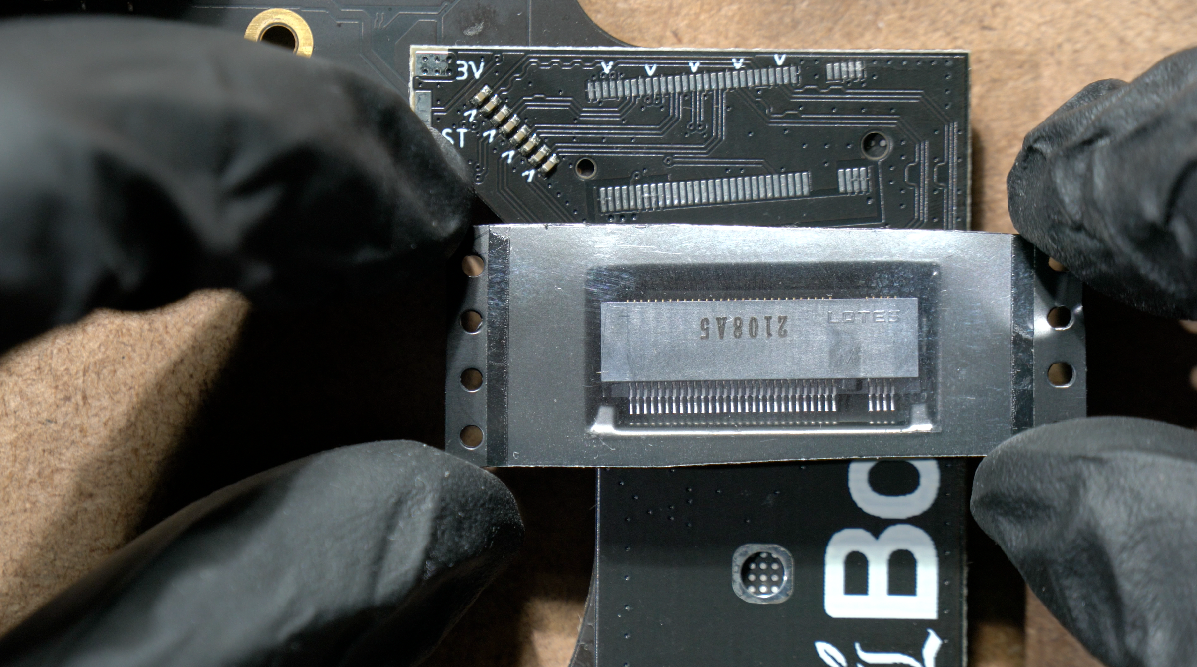
Take the M.2 female connector from the Kit, and take it out from the plastic.
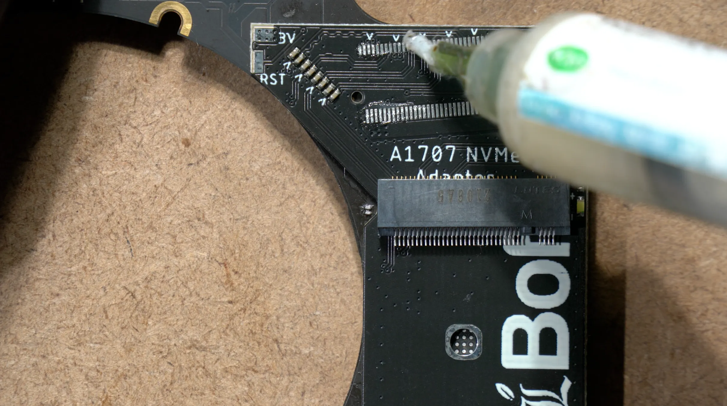
Apply flux to the M.2 footprint, and we're going to install it manually using soldering iron. You can try to install it using hot air gun for much faster results, but you will risking it to melt and not have the best cosmetic(you've been warned, unless you're an expert)
Put the M.2 connector into the PCB holes, push the M.2 connector all the way up to make space for the 2242 SSD. It will be a really tight space for 2242 SSD, unless youre planning to use 2230 SSD. Begin to solder anchor for the M.2 connector.
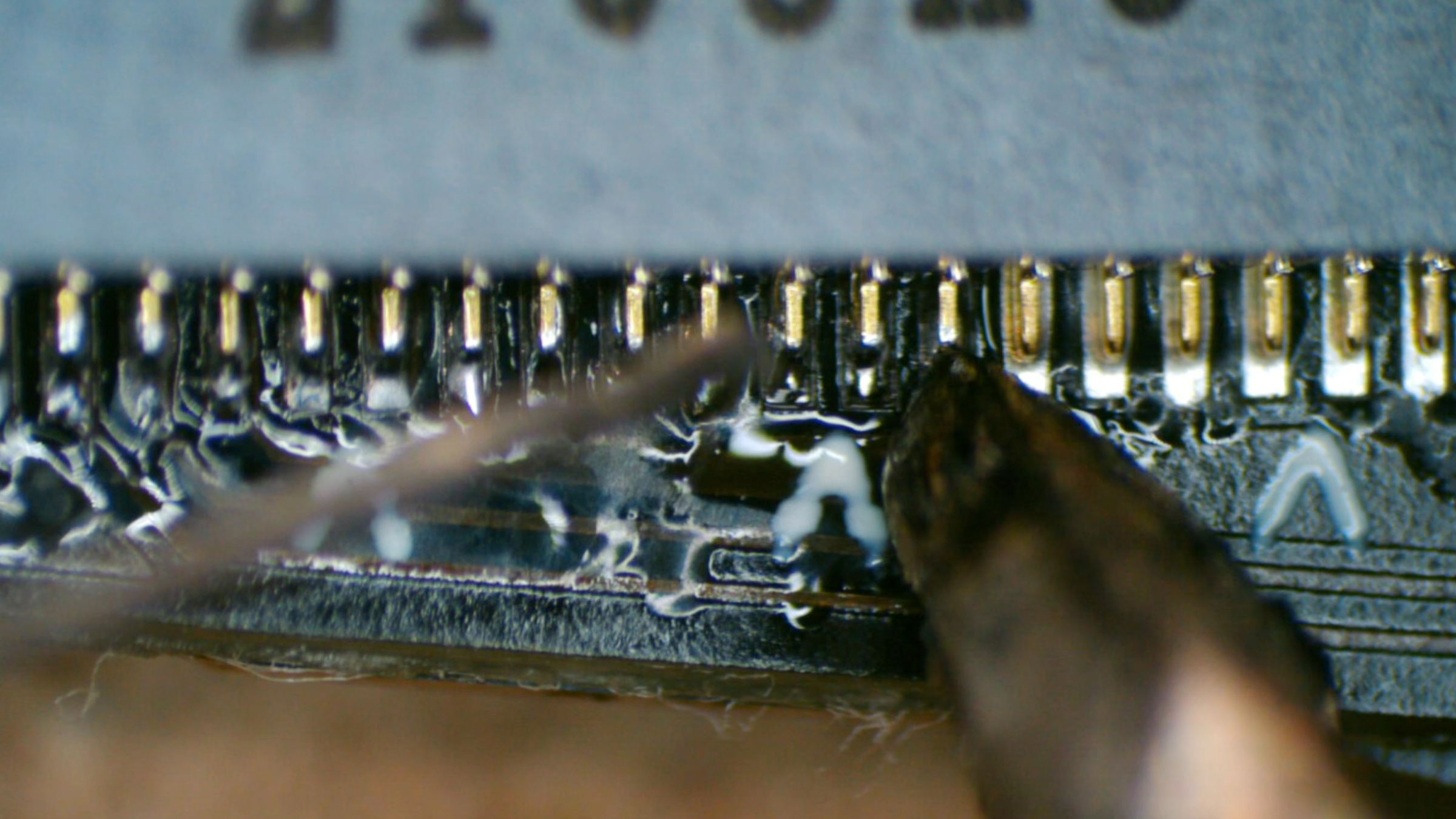
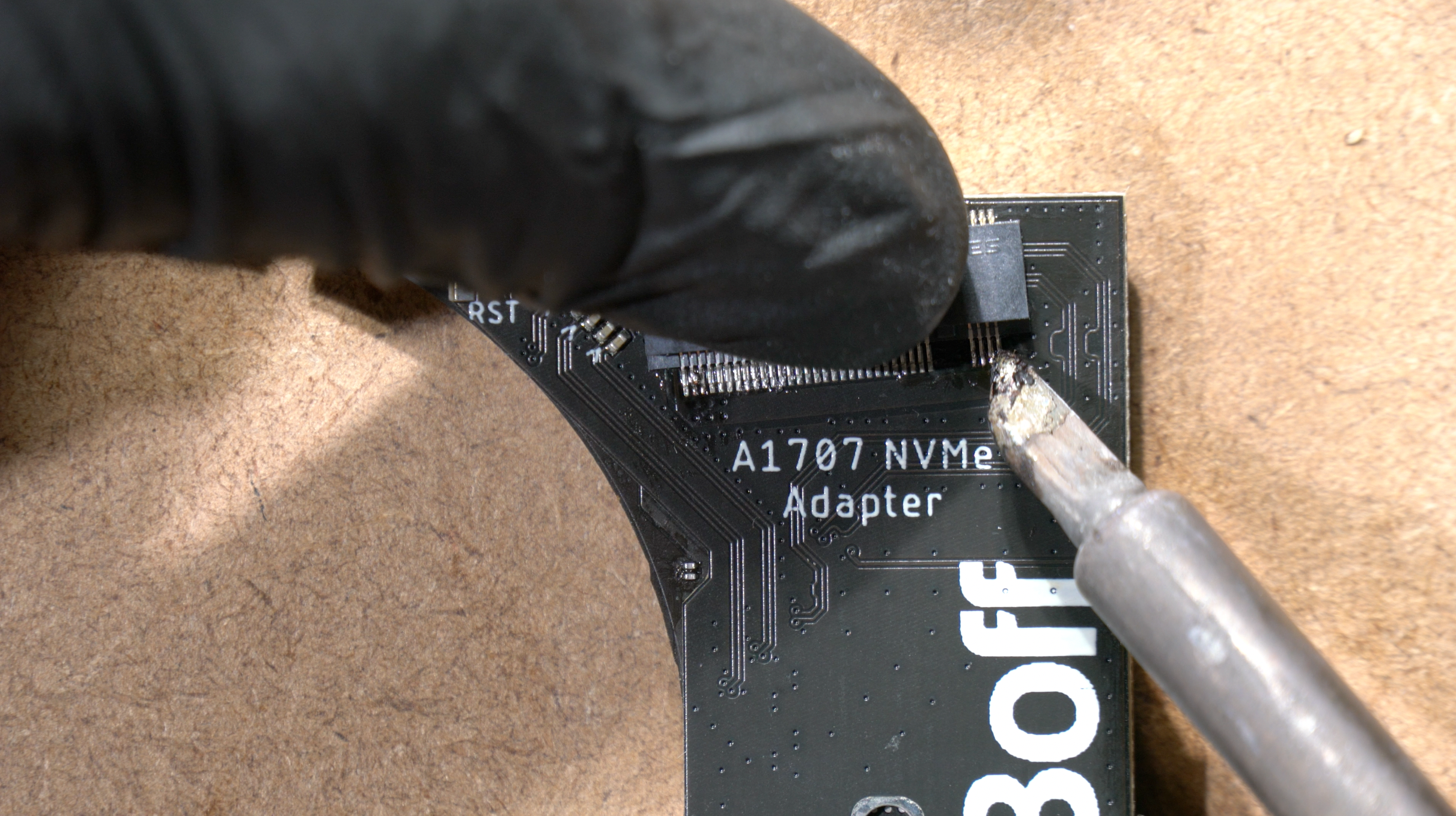
Solder the M.2 pins one by one & flux.
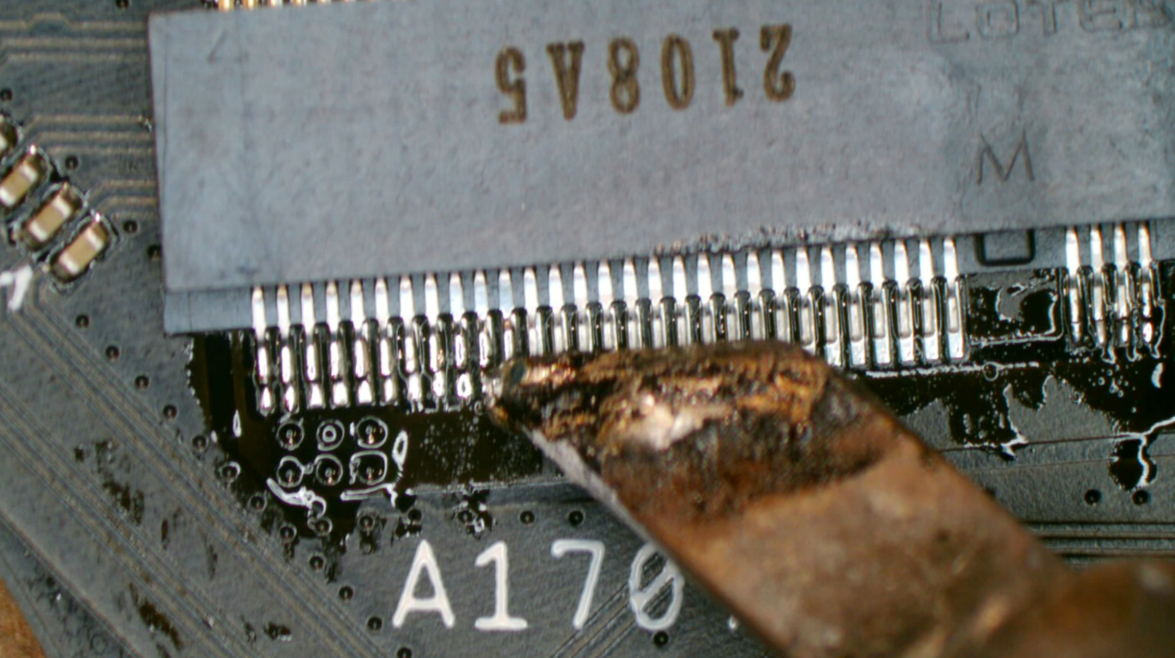
Almost there...
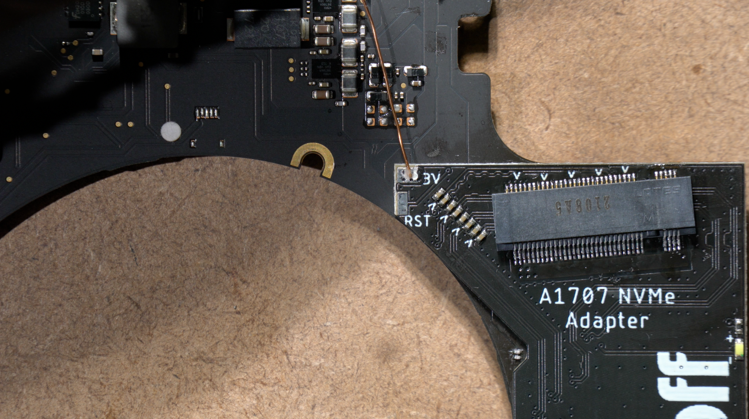
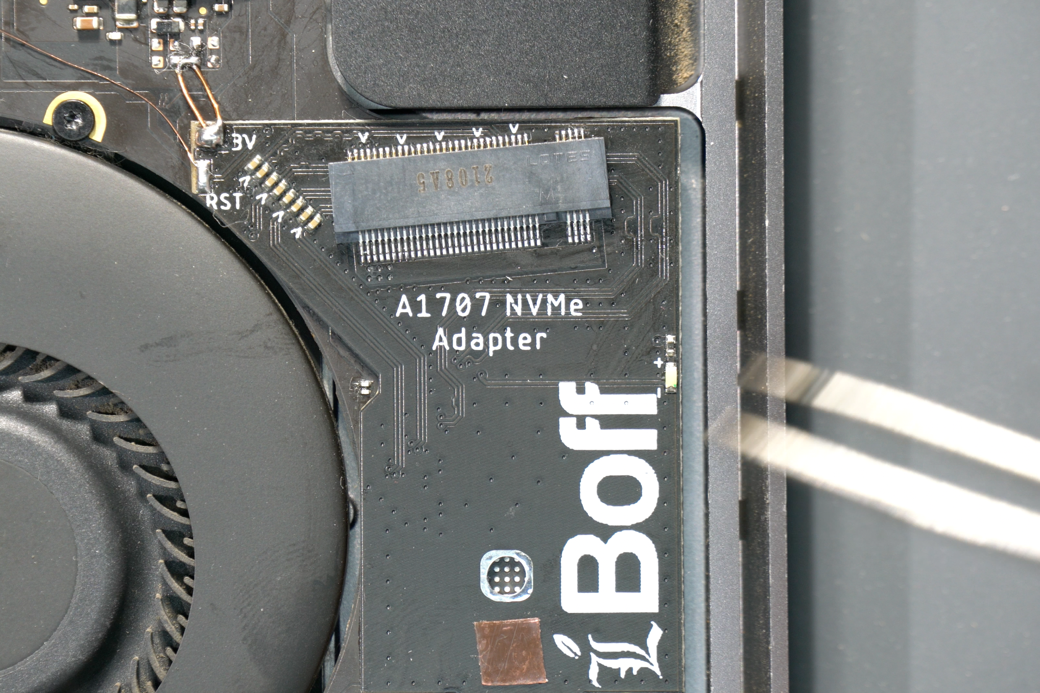
After you finish soldering the M.2 connector, you need to solder the 3V pad to PP3V3_SSD_LIM using a jumper wire. You need to use a larger wire than 0.1mm, like the copper core wire etc. If you still want to use 0.1mm, you need to make several turns.
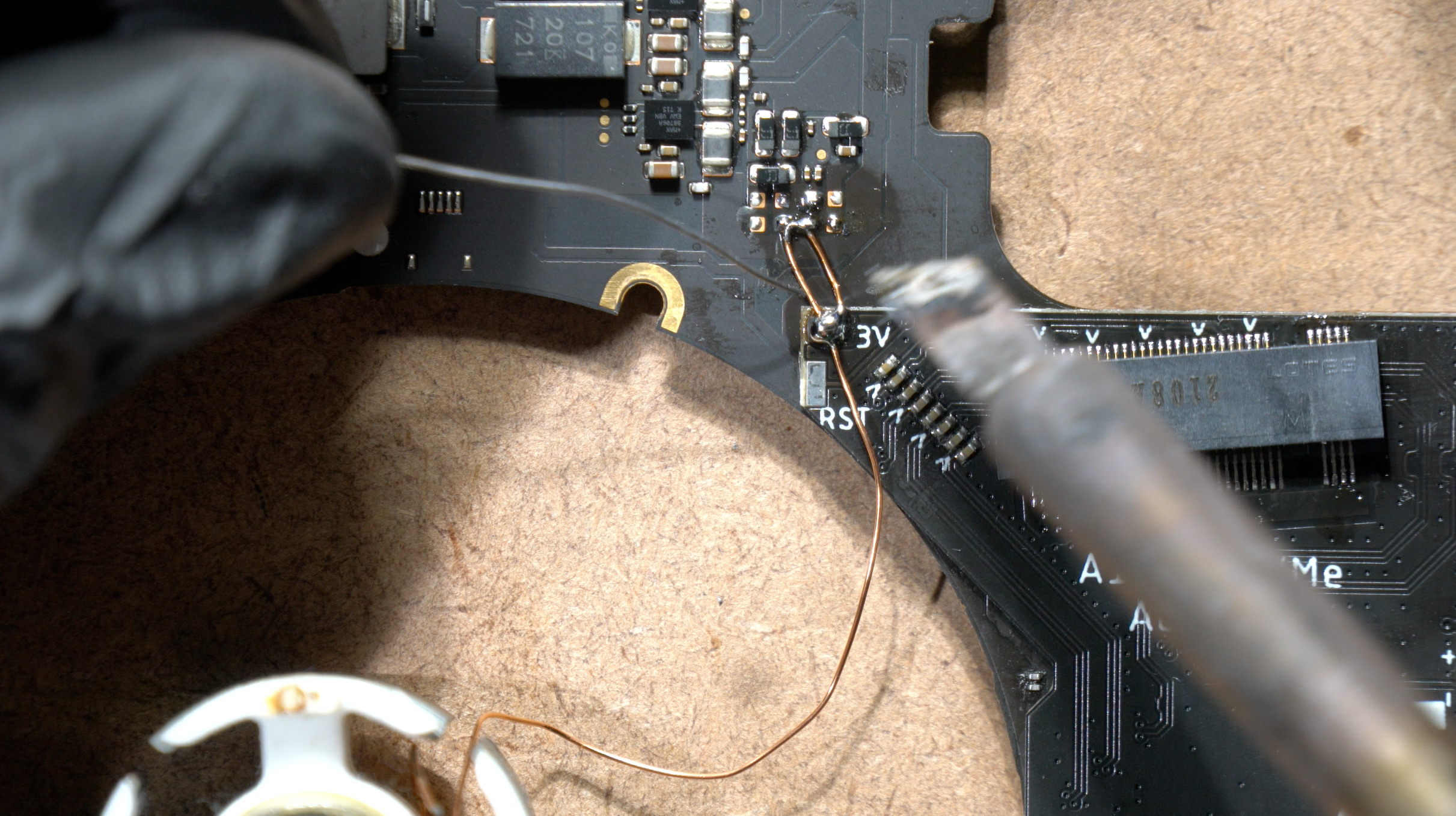
0.5mm core wire with 2 turns.
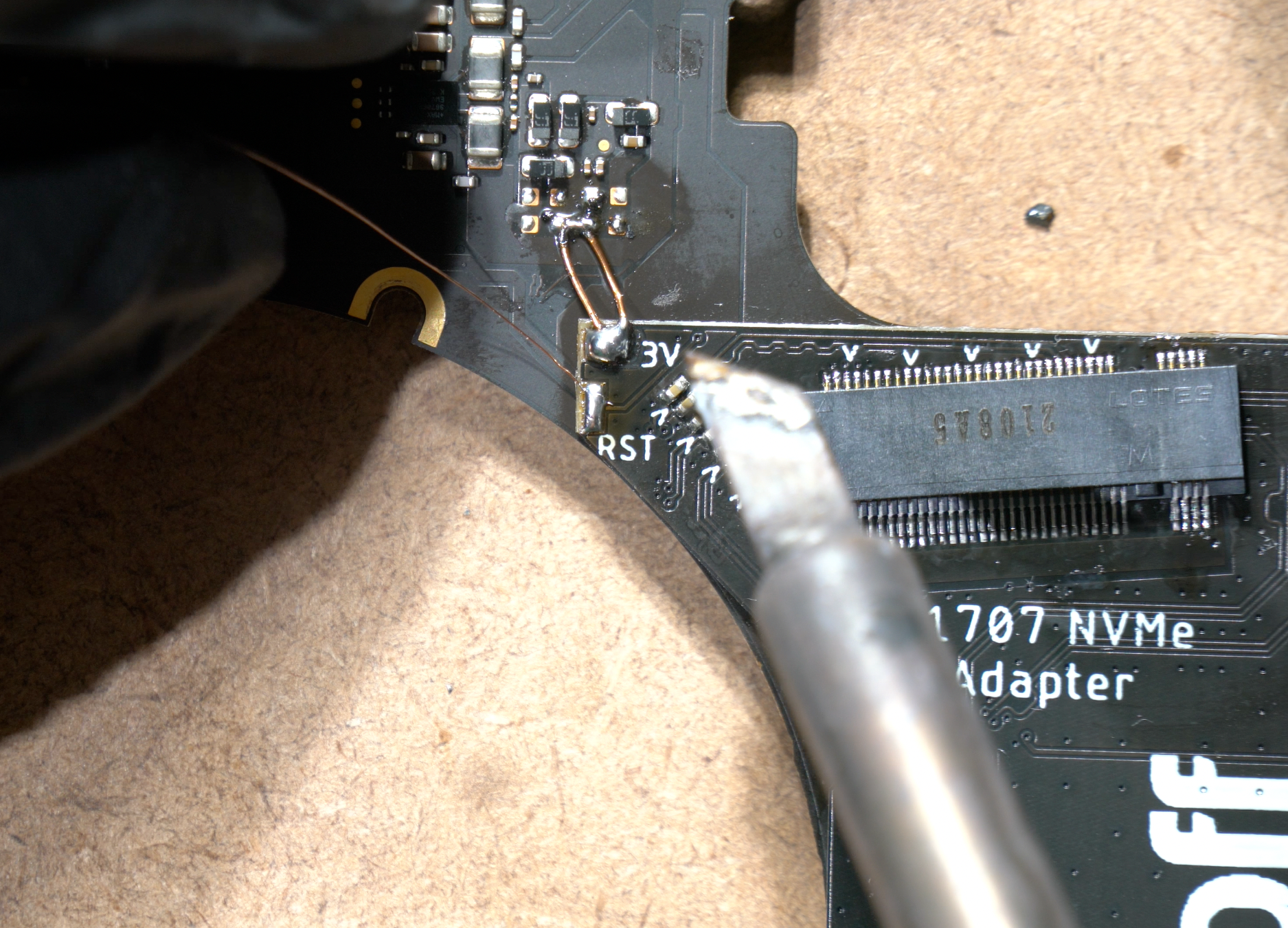
Solder 0.1mm jumper wire from RST pad on the Adapter to SSD_RESET_LB_L.
SSD_RESET_LB_L testpoint.
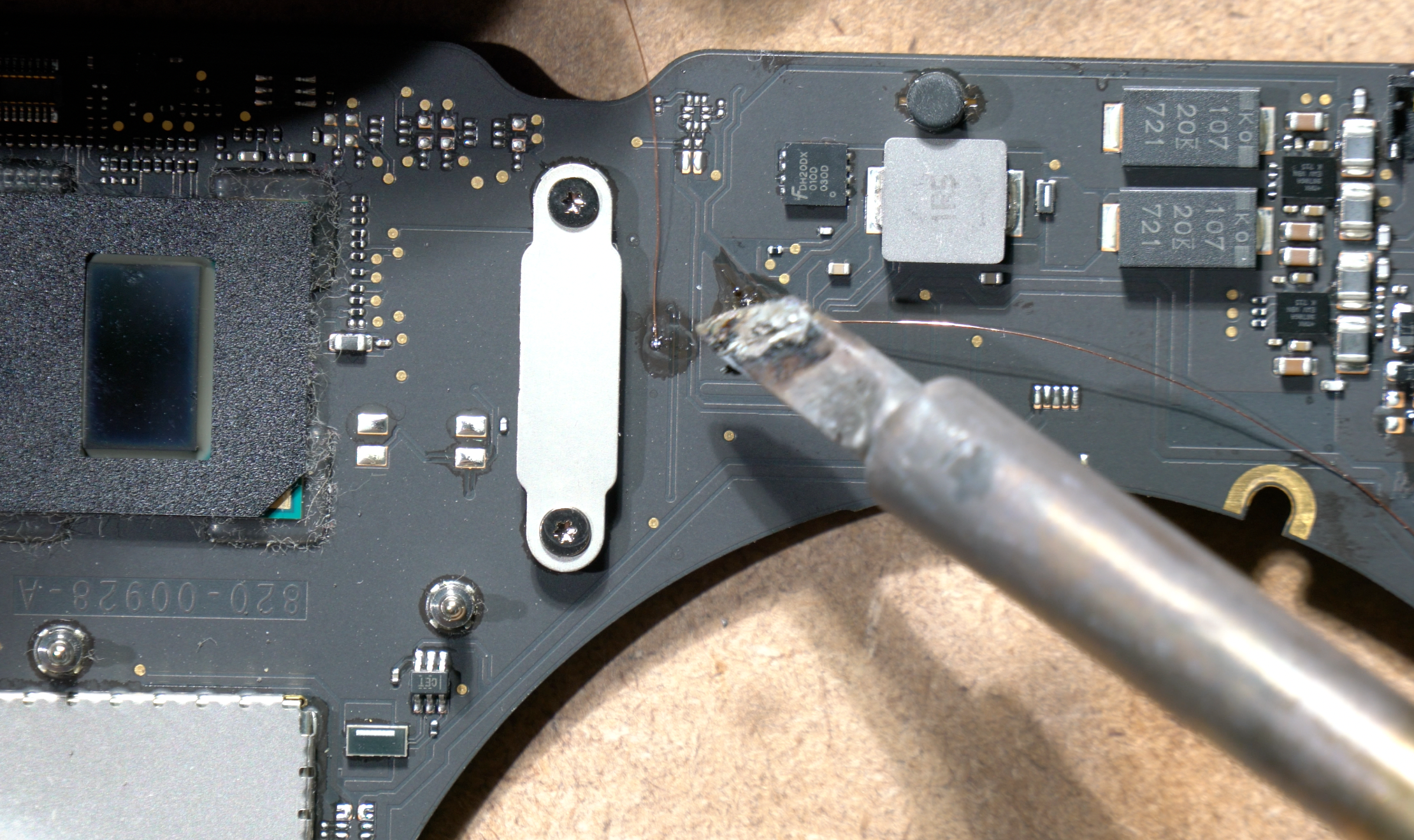
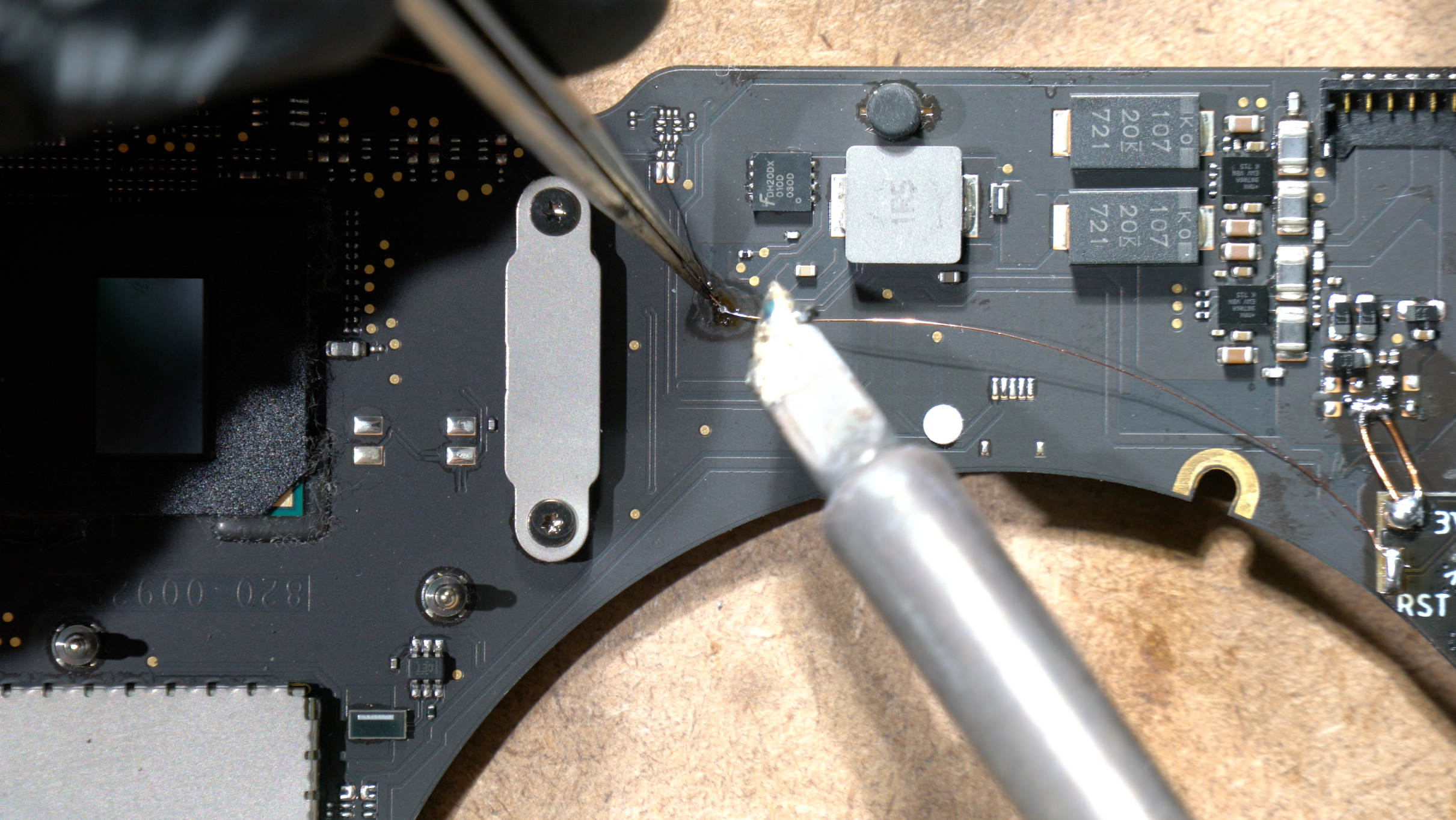
Next, solder jumper wire from SSD_CLKREQ_LB_L to any nearby GND pins (pull down to GND)
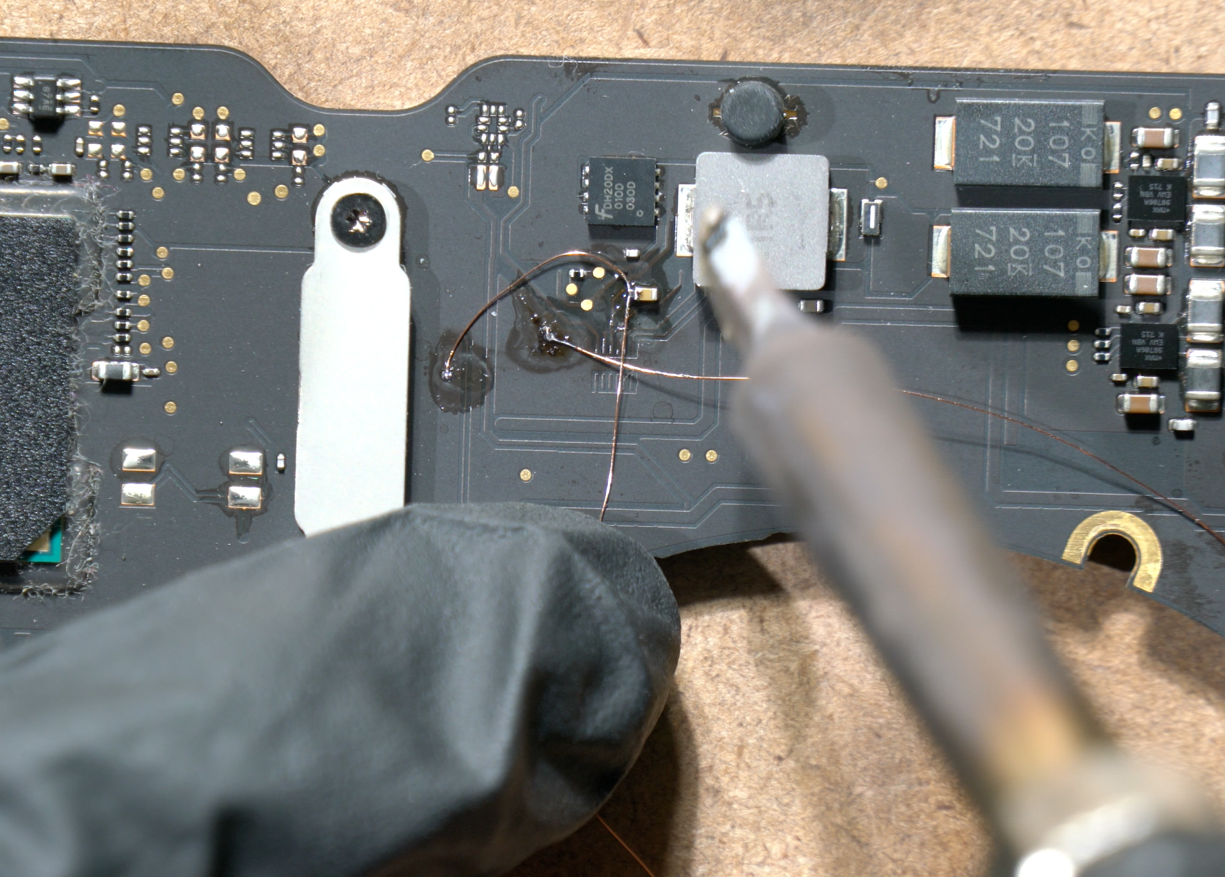
You can choose any GND pins on the board, this one we solder it to CB700 GND.
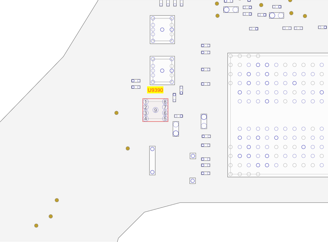
Optional: you can remove U9390 to save power, by cutting 3.3V_LIM supply to the remaining onboard NANDs.
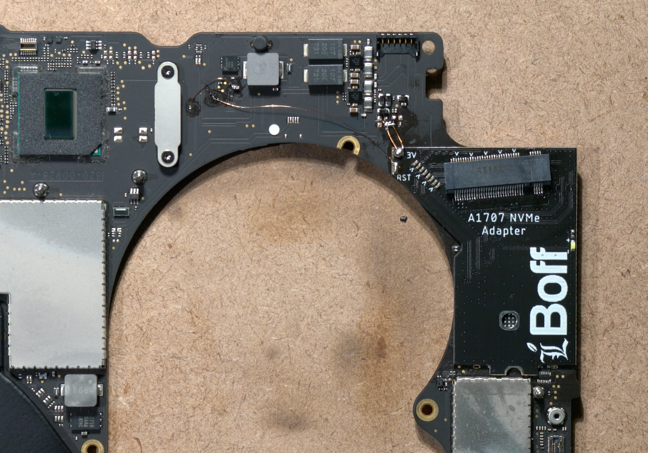
Here is the final result! This is the end of soldering phase, and you can clean all the flux and use ultrasonic cleaner if you want to. You can also cover the exposed copper wires with conformal coating.

To test whether the M.2 port is functional or not, we're gonna plug in an NVMe SSD with MacOS preinstalled in it.
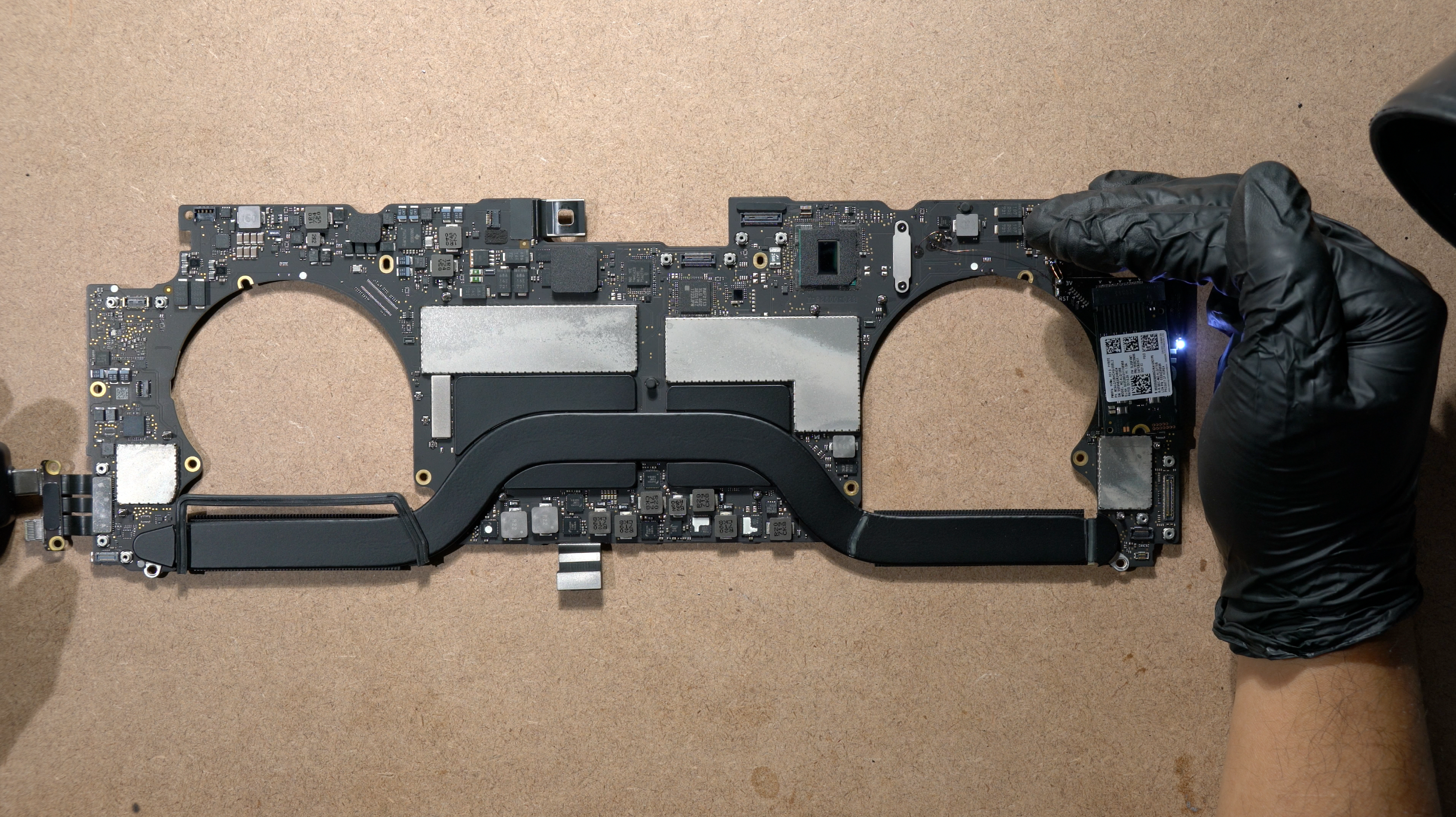
Plug in the USB-C charger, and the LED light will starts to blink when the MLB turns on and reads the NVMe drive.
REASSEMBLING STAGE
Reinstall the MLB into the chassis as you usually do,
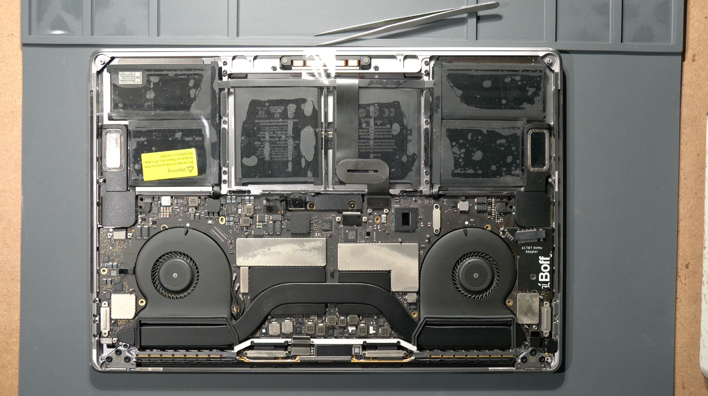
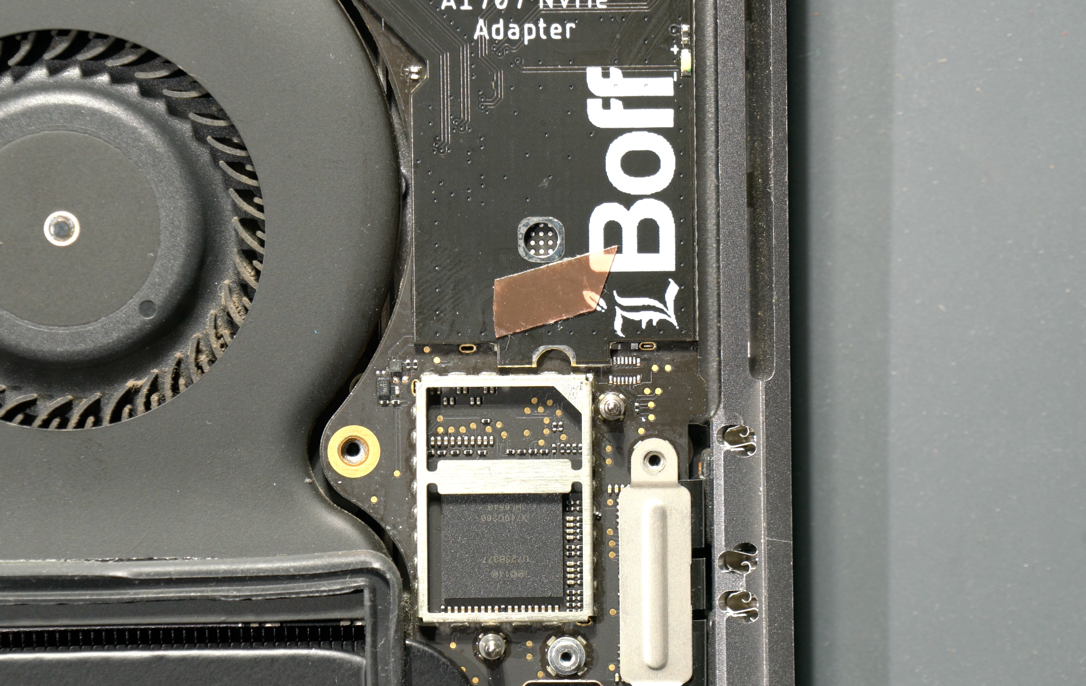
So there's not much difference on how it looks like originally except the M.2 NVMe connector on the right.
So now we will try to fit 2242 SSD into the M.2 slot.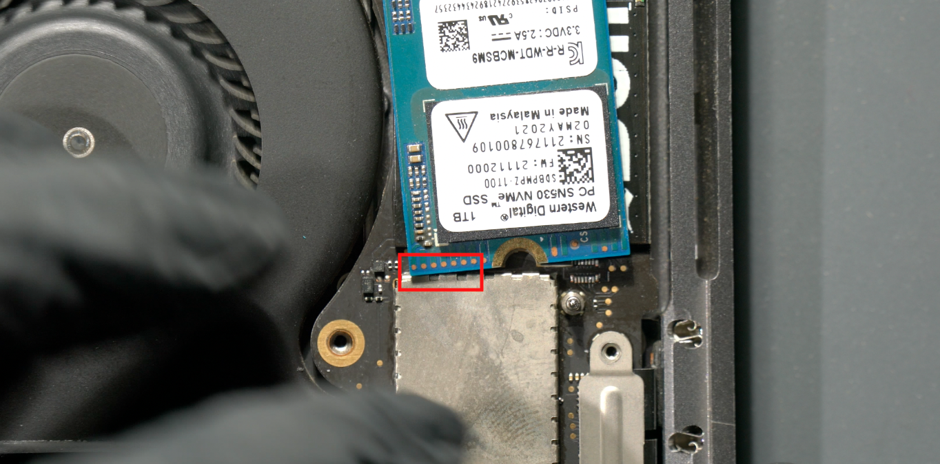
If you look closely, the 2242 SSD can barely fit the tight space.
So you have to pry up EMI shield on the Thunderbolt chip, and modify it a bit.
Exposed TBT chip with no EMI shield, and you will see the 2242 SSD now fit into the space.
Take the EMI shield and cut off several "teeths" like the following picture.
Picture above: Modified EMI Shield
Tape the thin LCD tape to hold the SSD in place(yes, we learn well from Apple to tape everything and stuff). But the tape in the above picture is too much, you need to make it smaller to allow easier removal later.
This small tape size should be enough. REMEMBER, the foundation support for this PCB adapter is only 0.3mm balls. So make sure to be gentle with it as you remove/install the SSD, or else youre going to rip off the solder pads and done.
Turn on the Mac, the LED light should blink as usual,
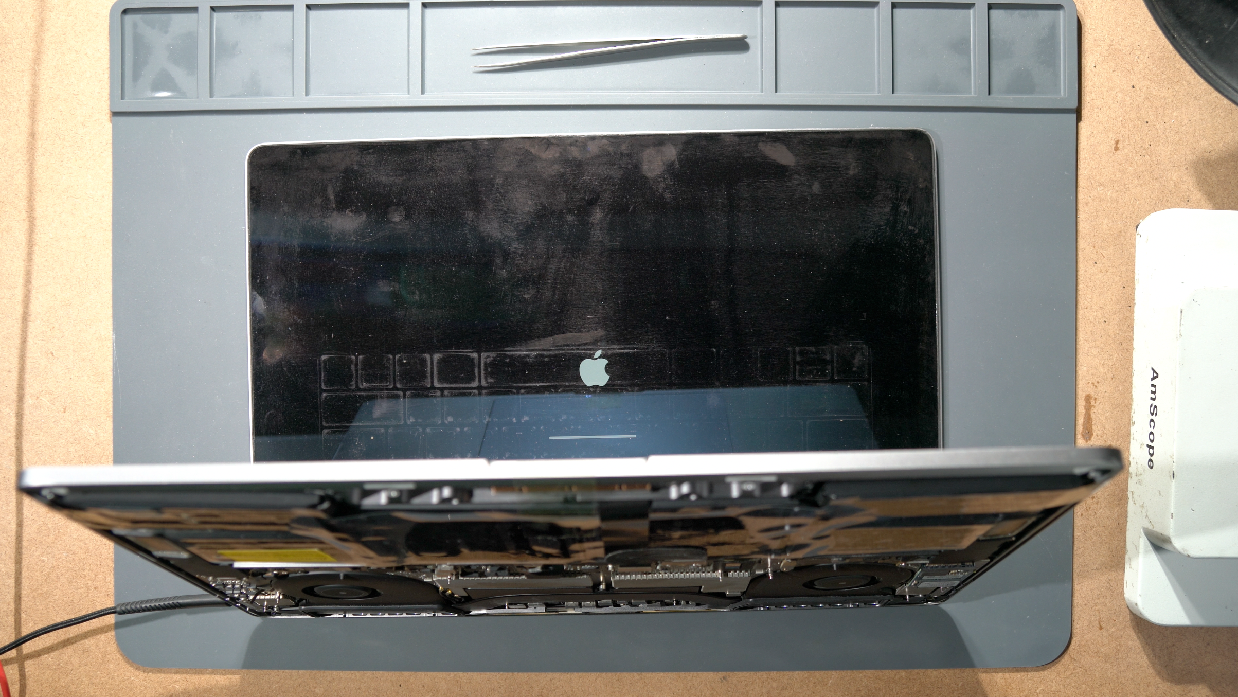
and start to boot MacOS installer as usual. This time we will be installing Ventura(only for 2017)
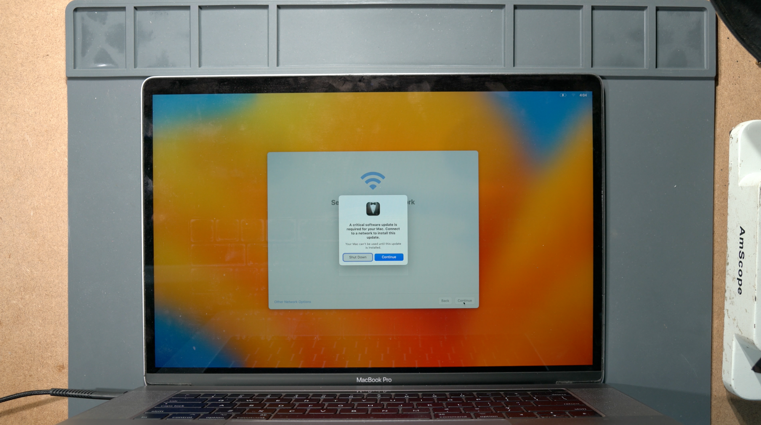
After you install MacOS like the standard procedure, and everything goes really well, then it will welcome you to Hello page, and as you go further it will ask you to connect to WIFI. This is where it will prompt "A critical software update is requred", because your 3rd party NVMe SSD is not native Apple SSD, and its missing the T1 Critical Software. But don't worry, it will download it from the Apple server and install it to your 3rd party NVMe.
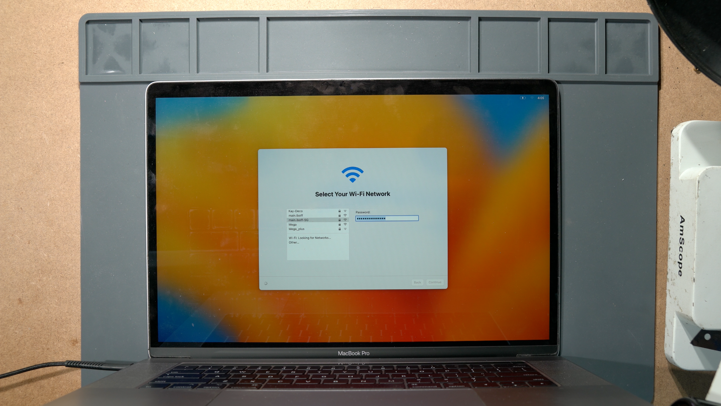
Key in the WIFI password, and let it download the necessary T1 Critical Software from their server. (you will never observe this kind of prompt in A1708 nontouchbar MacBook)

Let it install about 2 minutes.
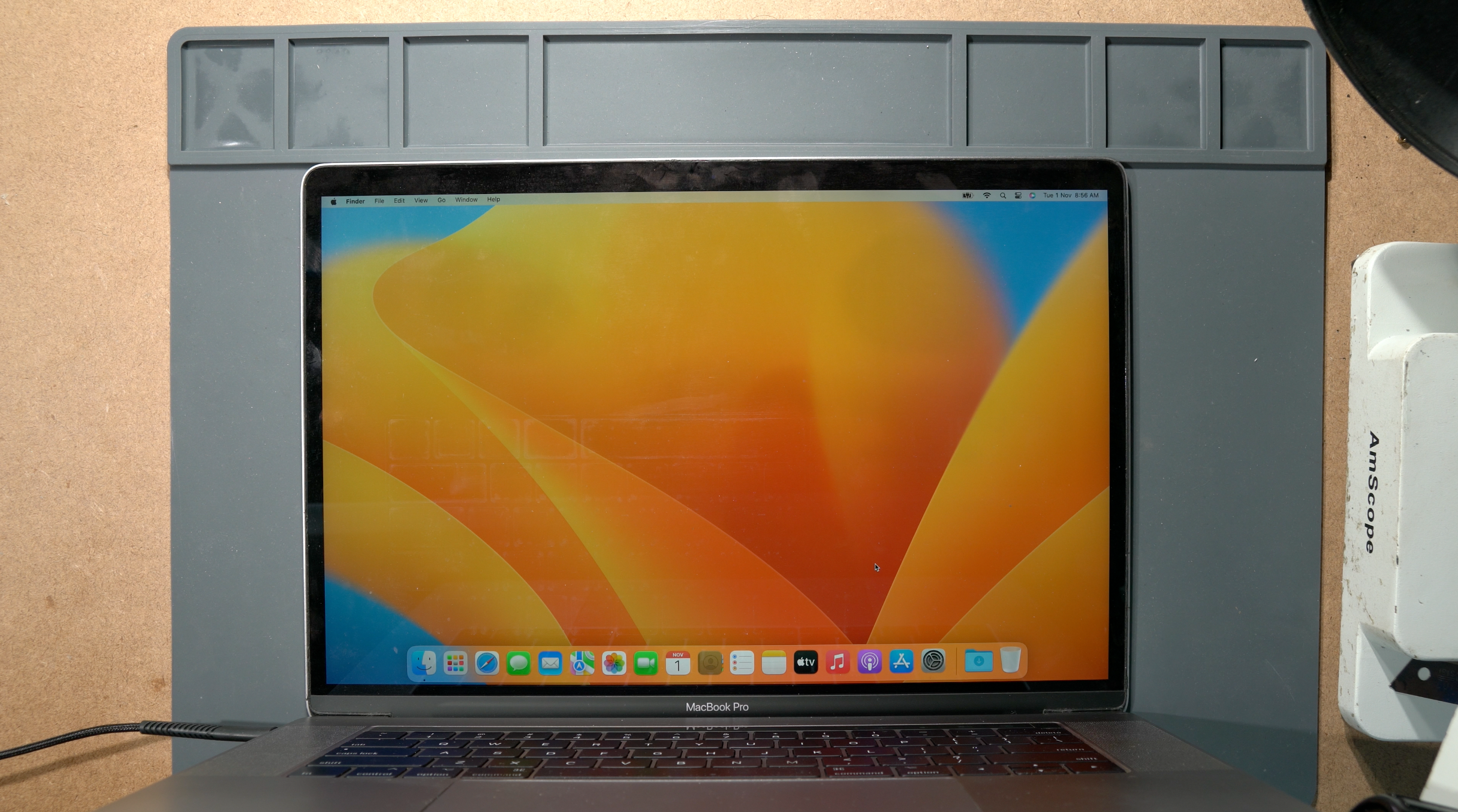
Andd youre done! You have a fully working A1707 with new, upgradable NVMe SSD!
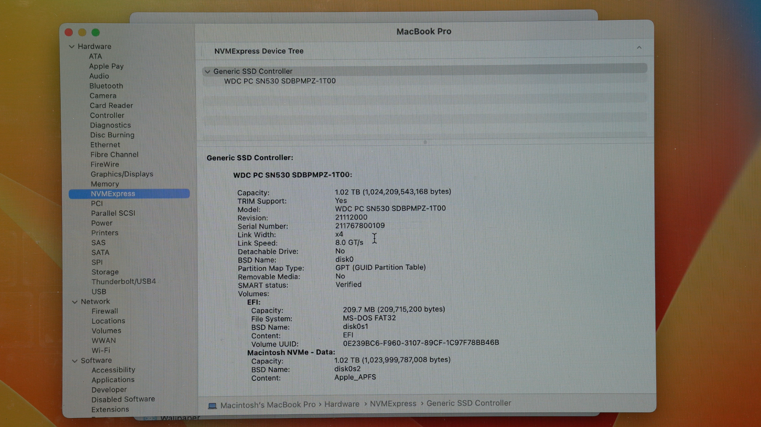
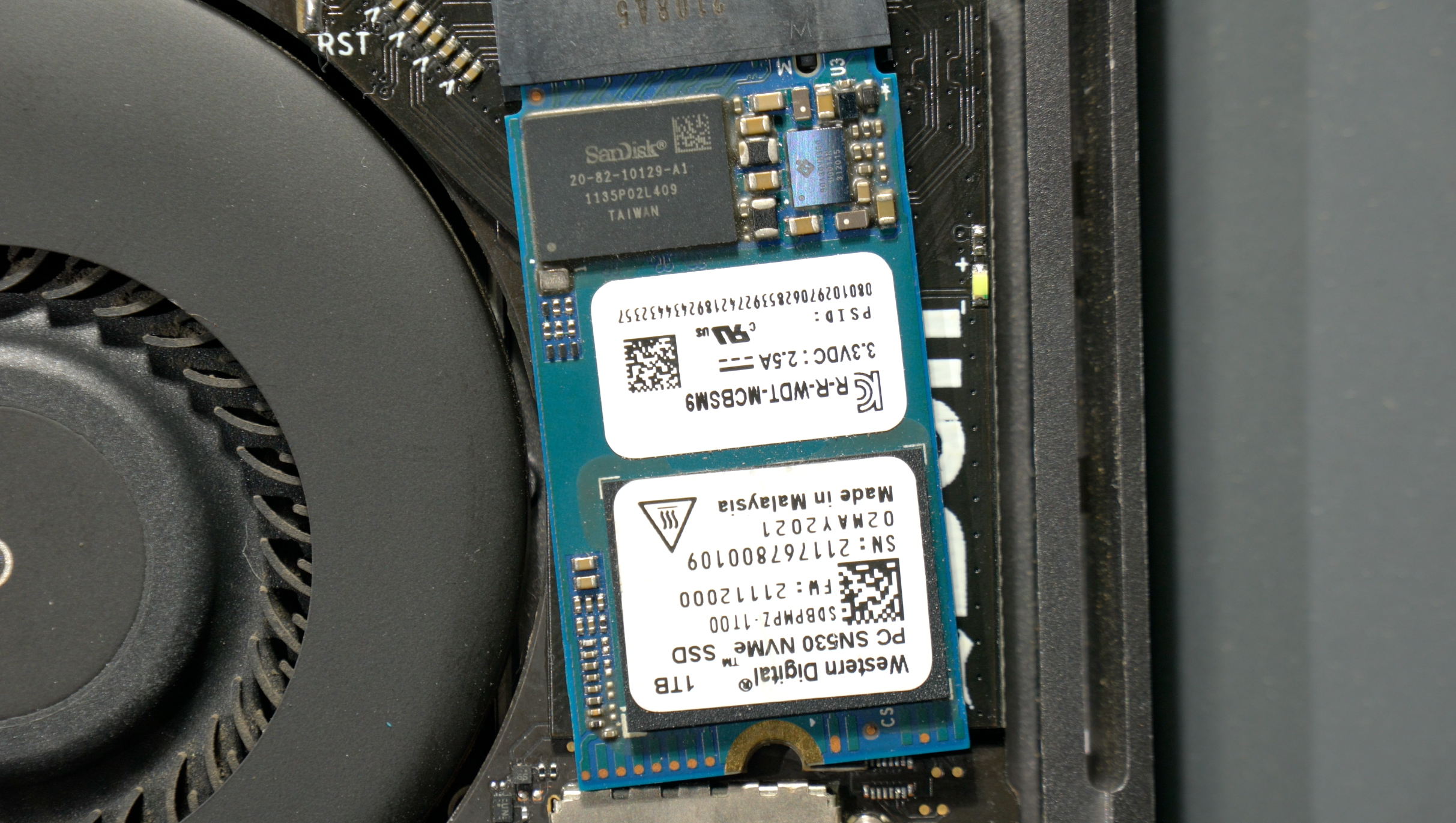
1TB 2242 NVMe SSD - WD SN530
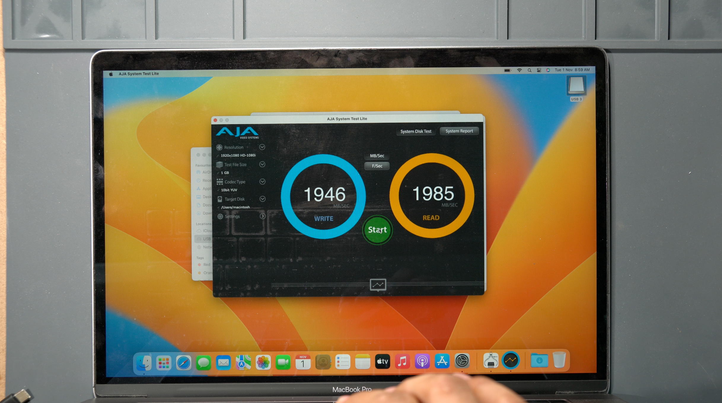
Speed test for the specific SSD.
If you read this far, THANK YOU! Have a nice day!